Bilateral Dislocation Differential Confocal Measurement Method

A differential confocal and measurement method technology, applied in the direction of testing optical performance, etc., can solve the problems of improving the resolution ability and other problems, and achieve the effect of improving the signal-to-noise ratio, improving the axial resolution ability, and high signal-to-noise ratio.

Active Publication Date: 2017-07-28
BEIJING INSTITUTE OF TECHNOLOGYGY
View PDF1 Cites 0 Cited by
  • Summary
  • Abstract
  • Description
  • Claims
  • Application Information

AI Technical Summary

Problems solved by technology

[0006] However, because the existing confocal microscope uses the confocal axial response characteristic curve 13 to fit the top data segment that is relatively insensitive to axial displacement to find its maximum position, the improvement of its resolving power is restricted.

Method used


Image

  • Bilateral Dislocation Differential Confocal Measurement Method
  • Bilateral Dislocation Differential Confocal Measurement Method
  • Bilateral Dislocation Differential Confocal Measurement Method

Examples


Embodiment 1

[0062] The specific steps of using the method of the present invention for fitting and measuring the height value of a single point are combined image 3 described as follows:

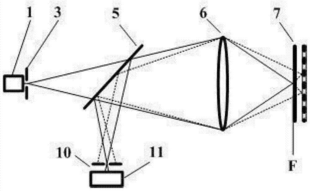
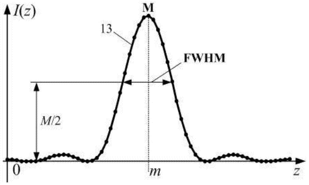
[0063] Step 1. Select a certain measurement point N(x,y) on the sample 7, make the objective lens 6 focus the spot to scan the measurement point axially, and at the same time, the photodetector 11 detects the confocal axial intensity of the sample axial position. The response value is 14, denoted as I(z), where x, y and z are the coordinates of the horizontal position and the axial height position of the sample measurement point, respectively;

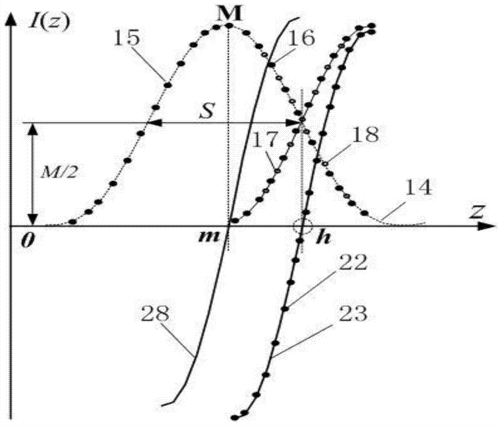
[0064] Step two, as image 3 As shown, determine the maximum value M of the confocal axial intensity response value 14, and divide the confocal axial intensity response value 14 into a left side data group 15 and a right side data group 16 with M as a boundary;

[0065] Step three, as image 3 As shown, the right side data group 16 does not move, so that the...

Embodiment 2

[0071] Under the scanning of the sample workbench, the method of the present invention is used to combine the measurement steps of point-by-point tomographic scanning imaging. Image 6 described as follows:

[0072] Step 1. Move the worktable 8 and record the horizontal position coordinates N(x, y) of the measured point of the sample 7;

[0073] In step 2, the objective lens 6 is fed in an axial step relative to the sample 7 along the optical axis direction, and the photodetector 11 measures the confocal axial intensity response value 14 corresponding to each axial feeding position;

[0074] Step three, as Figure 5 As shown, for each confocal axial intensity response value 14 obtained in step 2, the shifted confocal axial intensity response value 24 is obtained by translating S along the lateral coordinate, and the S value is selected as the confocal axial intensity response data set 14 half-height width FWHM of the curve;

[0075] Step four, as Figure 5 As shown in step...

Embodiment 3

[0083] Under the scanning of the sample workbench, the method of the present invention is used to combine the measurement steps of layer-by-layer scanning tomography. Image 6 described as follows:

[0084] Step 1. Focus the objective lens 6 on the first interface of the sample to be measured, and then move the worktable 8. In this interface, the photodetector 11 measures the photoelectric signal values ​​of all the points to be measured, and records the level of all the points to be measured. Position coordinates;

[0085] Step 2: According to the sample measurement accuracy requirements, select the micro-feed step distance of the objective lens relative to the sample;

[0086] Step 3: Make the objective lens 6 carry out micro-step feeding relative to the sample 7 along the optical axis direction, and then move the worktable 8 precisely according to the coordinates of the horizontal position point recorded in the step 1, so that the focusing spot of the objective lens is ali...


PUM


Abstract

The invention belongs to the technical field of optical imaging and detection, and relates to a bilateral misalignment differential confocal measurement method. The method accurately obtains the position of the extremum point of the confocal system characteristic curve through the misalignment and differential subtraction processing of the data sets on both sides of the confocal axial characteristic curve itself. Since the present invention utilizes two segments of data that are very sensitive to axial displacement near the half maximum width of the confocal characteristic curve to perform differential subtraction processing, the extreme point position of the confocal characteristic curve deduced from the data segment Compared with the top fitting method of the existing confocal characteristic curve, the sensitivity is greatly improved. As a result, the axial resolution and signal-to-noise ratio of the existing confocal microscope system can be significantly improved without changing the structure of the confocal microscope system. The invention will provide a new technical approach in the field of confocal imaging / detection.

Description

technical field [0001] The invention belongs to the technical field of optical imaging and detection, and relates to a bilateral misalignment differential confocal measurement method. Three-dimensional microstructures, microsteps, microgrooves, integrated circuit line widths, surface topography, and surface measurement and positioning can be used. Background technique [0002] The idea of ​​confocal microscopy was first proposed by American scholar M.Minsky in 1957, and he obtained the US patent in 1961, the patent number is US3013467. The confocal microscope places the point light source, point object, and point detector in corresponding conjugate positions, forming an optical microscopic imaging system with unique tomographic capabilities of point illumination and point detection in optical microscopic imaging. [0003] The basic principles of confocal microscopy are figure 1 As shown, the light emitted by the light source 1 passes through the pinhole 3, the beam splitte...

Claims


Application Information

Patent Timeline
Patent Type & Authority Patents(China)
IPC IPC(8): G01M11/02
Inventor 赵维谦邱丽荣王允
Owner BEIJING INSTITUTE OF TECHNOLOGYGY
Why Eureka
Try Eureka