Section structure of lightweight car body and application method thereof

A lightweight, car body technology, applied in the superstructure, superstructure sub-assemblies, vehicle components, etc., can solve the problems of sheet metal without relevant supporting structure, increased dent resistance strength, and large vehicle air conditioning load, etc., to reduce The effect of body quality, enhanced bending rigidity, and strong noise isolation

Inactive Publication Date: 2015-05-06
HUNAN UNIV AISHENG AUTO TECH DEV
View PDF6 Cites 22 Cited by
  • Summary
  • Abstract
  • Description
  • Claims
  • Application Information

AI Technical Summary

Problems solved by technology

[0012] (1) A large number of transition flanges or welding laps in the traditional sheet metal body, there is a waste of materials due to non-practical functional structures, and the cost and assembly are difficult
[0013] (2) The non-welded buckle positions in the traditional sheet metal body often have a large range of sheet metal without related support structures, making the thin-walled sheet metal in these positions easy to sag after being stressed
For example, car doors, hair covers, and ceilings all have strength requirements for dent resistance. Satisfying the strength of dent resistance will inevitably increase the thickness of the plate or add ribs or complex curved surface structures at the expense of lightweight results.
[0014] (3) In the design process of traditional sheet metal body, a lot of manufacturing technology needs to be considered. The shape and depth of sheet metal stamping have their own technological limits. For example, the negative angle structure of the flanging cannot be designed and implemented.
[0016] (5) The sound insulation and thermal insulation performance of the traditional sheet metal body is insufficient
Affects the senses of the human body, the load of the car air conditioner is large, and the energy utilization rate is not high

Method used


Image

  • Section structure of lightweight car body and application method thereof
  • Section structure of lightweight car body and application method thereof
  • Section structure of lightweight car body and application method thereof

Examples


Embodiment approach

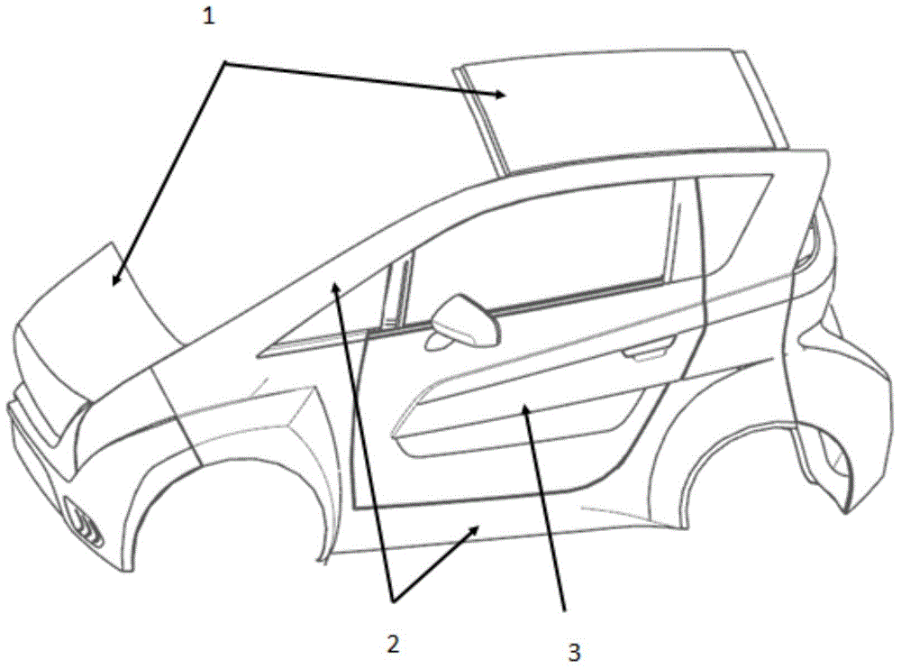
[0043] like image 3 As shown, the structure of the present invention is used to construct the method for the lower sill side beam of the car door, and the specific design and implementation plan is as follows:

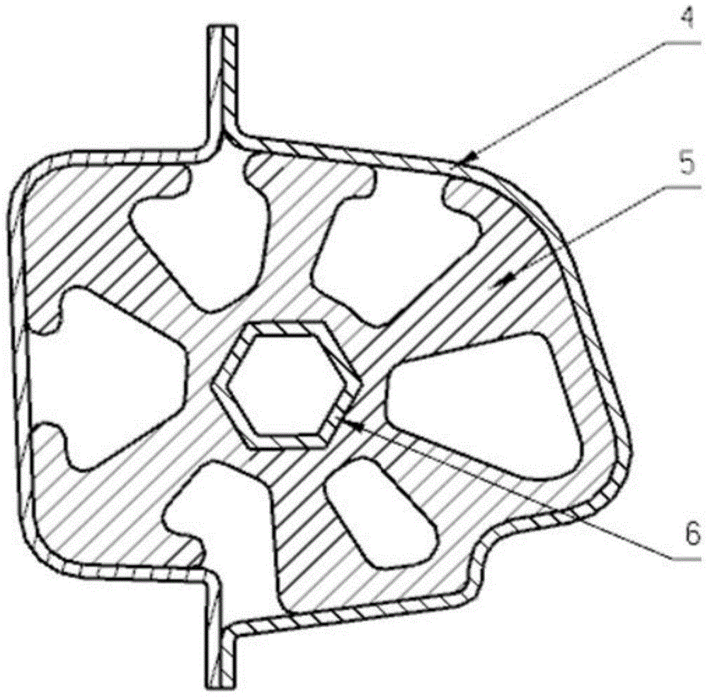
[0044] Step 1. The core layer 6 skeleton of the lower frame section of the front door frame of the vehicle body is formed by rolling, stretching, compression molding and other technological means to complete the shape formation;

[0045] Step 2. The core layer skeleton of the lower frame section of the front seat door frame of the vehicle body is shaped and adjusted to the size specifications by passing the 6 frames of the jig bracket;

[0046] Step 3. The core layer 6 skeleton of the lower frame section of the front door frame of the vehicle body is placed in the vehicle assembly fixture for use;

[0047] Step 4, 3D printing the middle layer 5 of the lower frame section of the front door frame of the vehicle body;

[0048] Step 5. Complete the assembly of the middl...


PUM


Abstract

The invention provides a lightweight car body structure, which comprises a core layer (300), a middle layer (200) and an outer layer (100), wherein the core layer (300) is a support framework which is made of aluminum magnesium alloy, the core layer (300) is of a hollow structure of which the section is in a circular, quadrilateral or hexagonal shape; the middle layer (200) is made of plastic, the middle layer is made into a rib structure through a 3D (three dimensional) print technology, and the rib structure is of a honeycomb structure, a mesh structure or a spatial cell body structure; the outer layer (100) is formed by adhering a carbon fiber sheet to the surface of the resin material. In the invention, the weight of the car body is reduced; the high-polymer carbon fiber material and the aluminum magnesium alloy are rationally applied to the structure design of the car body, and properly replace the previous sheet metal structure material; in the condition of guaranteeing the safe strength and rigidity property, the weight of the car body is reduced and the fuel consumption is reduced.

Description

technical field [0001] The invention relates to a section structure of an automobile body, in particular to a section structure of a vehicle body capable of reducing weight and a method for using the same. Background technique [0002] As "energy conservation and environmental protection" has increasingly become a topic of widespread concern, lightweight is also widely used in the field of ordinary vehicles, which can improve handling and also have excellent fuel-saving performance. The fuel consumption of a car mainly depends on the displacement of the engine and the total mass of the car. On the premise of keeping the overall quality, performance and cost of the car unchanged or even optimized, reducing the weight of the car itself can increase output power, reduce noise, improve handling, and reliability. Performance, increase vehicle speed, reduce fuel consumption, reduce exhaust emissions, and improve safety. According to research figures, if the weight of the vehicle ...

Claims


Application Information

Patent Timeline
Patent Type & Authority Applications(China)
IPC IPC(8): B62D29/04B62D25/00
CPCB60J5/04B62D25/02B62D29/005
Inventor 高晖罗庚杨兴
Owner HUNAN UNIV AISHENG AUTO TECH DEV
Why Eureka
Try Eureka