Cavity solar receiver with lighting cover

A technology for daylighting covers and solar energy, which is applied to solar collectors, solar collectors using working fluids, and solar thermal energy. Thermal efficiency, solving the effect of spot shifting and reducing heat loss

Active Publication Date: 2015-05-06
STATE GRID CORP OF CHINA +3
View PDF7 Cites 5 Cited by
  • Summary
  • Abstract
  • Description
  • Claims
  • Application Information

AI Technical Summary

Problems solved by technology

[0004] Prior to the present invention, Chinese patents such as Patent Nos. 200610039125 and 200980145350 all disclosed a cavity-type solar receiver, but its structure is complex and its volume is small. It is usually used in systems using air as a heat transfer medium, and the scale of power generation is not large. Big
Considering the small heat capacity of air, the equipment is easily damaged due to excessive temperature
At the same time, the Chinese patent No. 201010574469 discloses a heat pipe tower solar receiver. Although the heat pipe is used as the heat transfer element, the efficiency is high, but from the structural point of view, the sun's rays enter from the bottom of the receiver through the heliostat. In the cavity, the heat pipes are vertically distributed around the cavity, so that the light cannot be incident on the heat pipes vertically, resulting in uneven distribution of irradiance on the heat pipes, which may lead to local overheating of the heat pipes
At the same time, due to the small light inlet, the tracking accuracy of the heliostat is very high, which increases the technical difficulty and cost investment

Method used


Image

  • Cavity solar receiver with lighting cover
  • Cavity solar receiver with lighting cover
  • Cavity solar receiver with lighting cover

Examples


Embodiment Construction

[0029] The core of the present invention is to provide a cavity-type solar receiver with a daylight cover. The present invention will be further described below in conjunction with the accompanying drawings. It should be understood that these embodiments are only used to illustrate the present invention and are not intended to limit the scope of the present invention. After reading the present invention, modifications to various equivalent forms of the present invention by those skilled in the art fall within the scope defined by the claims of the present application.

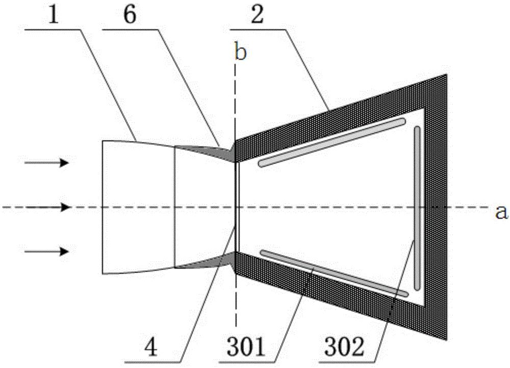
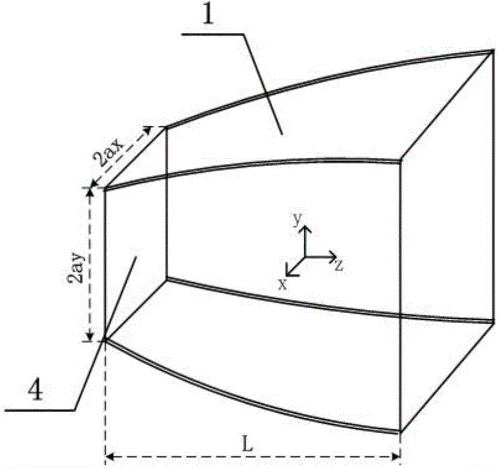
[0030] as attached figure 1 As shown, the structure of the present invention mainly includes a rectangular compound parabolic daylighting cover 1, a quadrangular prism-shaped cavity 2 and a heat-absorbing tube panel. Heat-absorbing tube screens are arranged on the remaining three sides, and the upper and lower bottom surfaces are heat-insulating surfaces. The light inlet 4 is relatively small, and the rear sid...


PUM


Abstract

The invention discloses a cavity solar receiver with a lighting cover. The cavity solar receiver comprises the lighting cover (1), a quadrangular prism type cavity (2) and heat absorption tube panels (3). A light inlet (4) is formed in the side face of the quadrangular prism type cavity (2), the evaporation tube panels (301) are arranged on a left side wall and a right side wall, and the overheating tube panel (302) is arranged on a rear side wall. The evaporation tube panels (301) and the overheating tube panel (302) are in linkage with a steam pocket (5) through upper and lower headers to form a steam and water loop. The lighting cover (1) is in a rectangular complex paraboloid type and is installed on the cavity (2) through fixing supports (6). The cavity receiver is simple in structure, the lighting area is increased, the convection loss of the light inlet is reduced, and the requirement for precision control over a tracking system is lowered.

Description

technical field [0001] The invention relates to the field of tower-type solar thermal power generation, in particular to a cavity-type solar receiver with a daylight cover. Background technique [0002] Tower-type solar thermal power generation technology uses an array of heliostats that can be automatically tracked to focus sunlight onto a receiver placed on a high tower. The heat transfer fluid in the receiver absorbs solar radiation energy and generates high-temperature and high-pressure steam that enters the steam turbine. in doing work. Compared with the trough type and the dish type, the tower type solar thermal power generation system has the advantages of high concentration multiple, energy concentration, small heat sink area, large unit capacity, and high efficiency. It is the latest after the trough type solar thermal power station Commercially viable solar thermal power generation technology. [0003] In the tower solar thermal power generation system, the solar...

Claims


Application Information

Patent Timeline
Patent Type & Authority Applications(China)
IPC IPC(8): F24J2/05F24J2/24F03G6/06F24S10/40F24S10/70
CPCY02E10/44Y02E10/46
Inventor 冯炜王金平杜炜谈友飞王启扬邵方知林晨
Owner STATE GRID CORP OF CHINA
Why Eureka
Try Eureka