spwm signal generating circuit based on direct digital frequency synthesizer

A signal generation circuit and frequency synthesizer technology, applied in the direction of pulse duration/width modulation, etc., can solve the problems such as the inability to adjust the frequency and amplitude of the SPWM signal through program control, the limited computing power of the microprocessor, and the low carrier ratio. Achieve the effect of achieving stability and program control

Active Publication Date: 2017-03-08
重庆希诺达通信有限公司
View PDF4 Cites 1 Cited by
  • Summary
  • Abstract
  • Description
  • Claims
  • Application Information

AI Technical Summary

Problems solved by technology

The hardware analog circuit generation method is relatively traditional. The analog circuit mainly generates triangular waves and sine waves respectively by discrete devices, and then synthesizes the SPWM waveform through the comparator. The frequency and amplitude accuracy of the SPWM signal generated in this way are relatively high, but the disadvantage is the lack of control Due to the limitation of the selected analog devices, its frequency adjustable range is very small (usually the frequency bandwidth is only a few kHz), and the frequency and amplitude of the SPWM signal cannot be adjusted through program control, so it is not easy to integrate with the program control system. Integrate and form a closed-loop control system for application
With the development of microcontrollers, DSP (Digital Signal Processor, digital signal processor), FPGA (Field Programmable GateArray, field programmable gate array), SOC (System on a Chip, system-level chip, also known as system on chip) The emergence of advanced high-speed microprocessors makes it possible to program the microprocessor through software, and the microprocessor can calculate and directly output the SPWM waveform in real time. The way of software programming to generate the SPWM signal can save a large number of external analog circuits, so that the circuit system can be obtained. Simplified, and it is convenient to adjust the SPWM signal through program control; however, due to the limited computing power of the microprocessor, the SPWM waveform directly calculated by it often has low carrier ratio, large waveform distortion, poor signal stability, and large resolution. Disadvantages such as high system resource usage
[0005] It can be seen that due to the shortcomings of pure analog circuit solutions and pure software programming solutions for the generation of SPWM signals in the prior art, it is difficult for the generated SPWM signals to simultaneously meet the requirements of low waveform distortion and high accuracy of signal frequency and amplitude. , and the technical requirements such as large adjustable range of signal frequency, good stability, and small frequency resolution have become important factors that limit the technical performance development of sinusoidal pulse width modulation related products.

Method used


Image

  • spwm signal generating circuit based on direct digital frequency synthesizer
  • spwm signal generating circuit based on direct digital frequency synthesizer

Examples


Embodiment Construction

[0025] The technical solution of the present invention will be further described below in conjunction with the accompanying drawings.

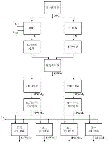
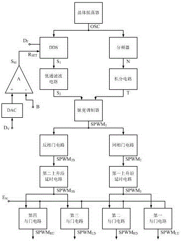
[0026] The present invention provides a kind of SPWM signal generating circuit based on direct digital frequency synthesizer, such as figure 1 As shown, including crystal oscillator, direct digital frequency synthesizer, low-pass filter, frequency divider, integration circuit, pulse width modulator, non-inverting gate circuit, inverting gate circuit, the first rising edge delay circuit, the first Two rising edge delay circuits and four AND gate circuits. Wherein, the crystal oscillator outputs a CMOS-level clock signal OSC to the clock signal input terminals of the direct digital frequency synthesizer and the frequency divider. The frequency setting input terminal D of the direct digital frequency synthesizer F Connect to frequency setting digital signal source, amplitude setting input R SET Connected to the amplitude setting analog signal ...


PUM


Abstract

The invention provides an SPWM signal generation circuit based on a direct digital frequency synthesizer. The SPWM signal generation circuit adopts the direct digital frequency synthesizer to generate sine-wave signals of a SPWM circuit, combines the synthesizer with triangular wave signals generated by an integral circuit, obtains bipolar SPWM signals through natural sampling, enables the distortion of the inverted restored sine-wave signals to be minimum, overcomes the defects that SPWM signals are generated by adoption of pure artificial circuits and pure software programming in the prior art by utilization of the characteristics of the direct digital frequency synthesizer, remains the advantages of the pure artificial circuits and the pure software programming in the prior art, enables the output SPWM signals to meet the technical requirements that the wave form distortion is low, the accuracy of the frequency and amplitude of signals is high, the adjustable range of the signal frequency is large, the stability is good and the frequency resolution is small, and effectively helps the development of the performance of the SPWM application technology.

Description

technical field [0001] The invention relates to the fields of electronic circuit technology and pulse modulation signal technology, in particular to a SPWM signal generating circuit based on a direct digital frequency synthesizer. Background technique [0002] Sinusoidal pulse width modulation (SPWM) is to change the modulation pulse mode on the basis of pulse width modulation (PWM), and the pulse width time duty cycle is arranged according to the sinusoidal law, so that the output waveform can be a sine wave after proper filtering output. It is widely used in DC and AC inverters, frequency converters, AC power supplies and other fields. Usually in these products, the SPWM signal is used to excite the full-bridge conversion circuit, and then the sine wave signal is obtained after low-pass filtering, and passed through the whole machine. Signal output output. [0003] However, in many application fields of products related to sinusoidal pulse width modulation, there are hig...

Claims


Application Information

Patent Timeline
Patent Type & Authority Patents(China)
IPC IPC(8): H03K7/08
Inventor 王光智陈清华平志礼李佳坤
Owner 重庆希诺达通信有限公司
Why Eureka
Try Eureka