QDF (quiescent direct furnace) direct reduction technology

A process and direct technology, applied in the field of direct reduction process, can solve the problems of high thermal shock resistance, unstable working conditions, difficult feeding, etc., to achieve uniform reducing atmosphere, reduce energy consumption and cost, and extend large walls. effect of life

Inactive Publication Date: 2015-05-20
WISDRI ENG & RES INC LTD
View PDF7 Cites 9 Cited by
  • Summary
  • Abstract
  • Description
  • Claims
  • Application Information

AI Technical Summary

Problems solved by technology

[0007] (1) Shaft furnace is used for direct reduction. During the reduction process, the reduction chamber is continuously loaded. During the reduction process, the materials are in a dynamic process, which requires high strength of the pellets. The reduced products are easy to stick, and the reduction time is limited; the reaction tank Refractory materials require high wear resistance, stress, and thermal instability, high temperature resistance, high thermal shock resistance requirements, and reduced furnace life; shaft furnace height is limited, feeding is difficult, production efficiency is low, and annual output is small , high construction cost per unit output;
[0008] (2) The reactor is divided into three sections: preheating zone, high-temperature reduction zone, and cooling zone. The temperature control in each zone is more difficult, the working conditions are unstable, the furnace type design is more complicated, the furnace material falling speed is difficult to control, and the production efficiency is low. ;
[0009] (3) The reduction chamber is tubular, and all the reaction tanks are located in the same combustion space. The combustion chamber has no specific shape. Since the position of each reduction chamber is different and the distance from the furnace wall burner is different, it is easy to cause different degrees of heating. , it is easy to have uneven temperature fields inside different reduction chambers, resulting in differences in products in different reduction chambers;
[0010] (4) Since all reduction chambers are in the same combustion space, when a single reduction chamber is overhauled, all furnaces need to be shut down, resulting in a plant-wide shutdown

Method used


Image

  • QDF (quiescent direct furnace) direct reduction technology
  • QDF (quiescent direct furnace) direct reduction technology
  • QDF (quiescent direct furnace) direct reduction technology

Examples


Embodiment approach

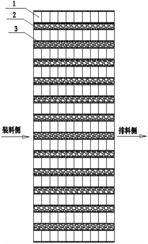
[0063] like Figure 2a As shown, a plurality of reduction chambers 2 and combustion chambers 1 are arranged at intervals, and a heat transfer partition wall 3 is arranged between adjacent reduction chambers 2 and combustion chambers 1. The temperature in each reduction chamber 2 is basically the same, which is suitable for treating a metal raw materials;

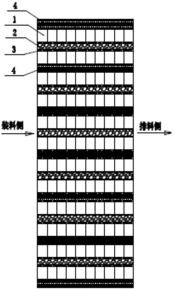
[0064] like Figure 2b As shown, a reduction chamber 2 is arranged in groups with two combustion chambers 1 located on both sides thereof, each group is separated by a large heat-insulating wall 4, and the temperature of each reduction chamber 2 can be independently controlled without being affected by each other. A variety of different metal-containing raw materials can be processed at the same time.

[0065] 5) The horizontal section of each reduction chamber 2 and combustion chamber 1 is trapezoidal or rectangular, and the vertical section is rectangular. The specific size of the reduction chamber 2 can be determined ac...

specific Embodiment

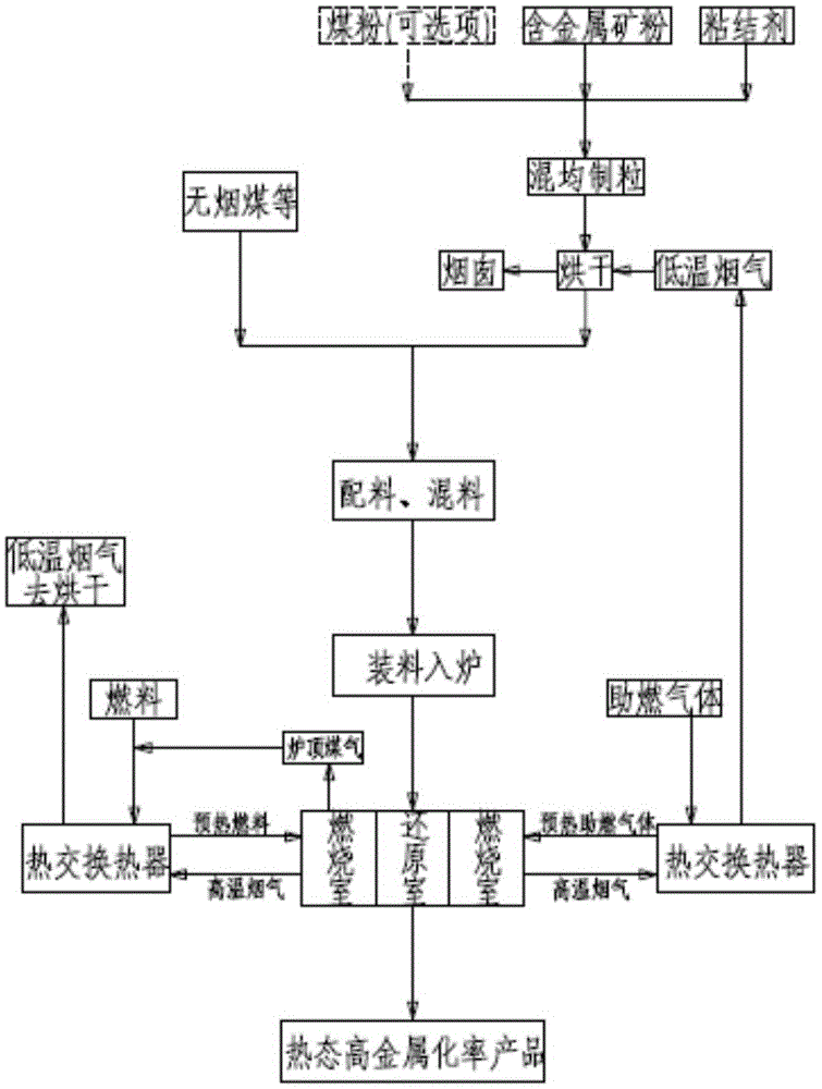
[0069] The specific embodiment of QDF direct reduction process of the present invention is as follows, comprises the following steps:

[0070] ST1: Fully mix the iron ore powder and binder with an iron content of more than 50% and then granulate it, with a particle size of about 30mm, dry it and transport it to the storage bin;

[0071] ST2: Mix the granular raw materials and anthracite reducing agent obtained above. The mass ratio of granular raw materials and reducing agent is about 1:0.3. , the bulk density is 2t / m 3 , the filling rate of the material in the reduction chamber is about 90%, and after the filling is completed, each feed port of the reduction chamber is automatically closed;

[0072] ST3: The reduction chamber is narrow and long, with a width of 300-550mm, a length of 5-18m, and a height of 3-8m;

[0073] ST4: The preheated gas supplied to the combustion chamber through the pipeline is 900°C and the preheated combustion air is 900°C;

[0074] ST5: Combustio...


PUM


Abstract

The invention relates to a QDF (quiescent direct furnace) direct reduction technology which comprises the following steps: uniformly mixing a metal-containing raw material and reducing agent powder, and putting into each reducing chamber, wherein in a reducing process, the reducing chambers and the reduced material are all kept in a stationary state; uniformly heating the materials in the reducing chambers by use of the heat generated by the combustion of the fuel in a combustion chamber and a combustion-supporting gas so as to perform a reduction reaction between the metal-containing raw material and the reducing agent, wherein each reducing chamber is a narrow long one-section reactor. According to the technology provided by the invention, the reducing chambers and the reduced material are all in a stationary state, the requirement on the strength of the granular raw material is reduced, and the production efficiency of a granulation process is improved; and the reducing time can be prolonged, and the metallization ratio of the reduction product is improved. The reducing chamber is not provided with a preheating area or a cooling area, the temperature is uniform, the atmosphere is uniform and consistent, and the overall quality of the reduction product is improved. The direct reduction technology has remarkable advantages of wide application range of raw materials, uniform temperature field, easy control on reduction process, high product metallization ratio, high yield and the like.

Description

technical field [0001] The invention relates to the technical field of metal pyrometallurgy, in particular to a direct reduction process. Background technique [0002] With the acceleration of the global industrialization process, the massive emission of CO2 gas has an increasingly significant impact on the environment and climate, and countries have increasingly stringent requirements for energy conservation and emission reduction in the industrial production process. Globally, the steel industry in the industrial field is Greenhouse gas emissions accounted for 15%, of which ironmaking system emissions accounted for 90% of the entire steel process emissions, mainly related to the long blast furnace ironmaking process and the large CO2 emissions in coking and sintering processes. Therefore, it is an inevitable trend of historical development to develop a new ironmaking process with short process, low pollution, low cost and environmental friendliness. [0003] At present, n...

Claims


Application Information

Patent Timeline
Patent Type & Authority Applications(China)
IPC IPC(8): C21B13/00
Inventor 夏锋周强秦涔
Owner WISDRI ENG & RES INC LTD
Why Eureka
Try Eureka