Check patentability & draft patents in minutes with Patsnap Eureka AI!

Negative voltage constant current source circuit

A constant current source and circuit technology, which is applied in the direction of adjusting electrical variables, control/regulation systems, instruments, etc., can solve the problems of unable to use negative pressure and generate constant current source, and achieve simple circuit, strong driving ability and few components Effect

Inactive Publication Date: 2015-05-27
XIAN DINGZI ELECTRONICS INFORMATION SCI & TECH
View PDF0 Cites 6 Cited by
  • Summary
  • Abstract
  • Description
  • Claims
  • Application Information

AI Technical Summary

Problems solved by technology

[0003] The purpose of the present invention is to overcome the problem in the prior art that negative pressure cannot be used to generate a constant current source, and to design an adjustable constant current source with the only negative pressure in the system

Method used


Image

  • Negative voltage constant current source circuit

Examples


Embodiment 1

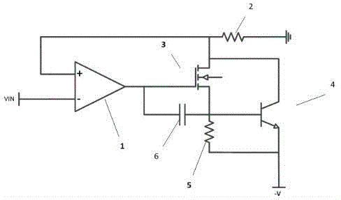
[0012] This embodiment provides a figure 1 The shown negative voltage constant current source circuit includes an operational amplifier 1, a load resistor 2, a high-power MOS transistor 3, a triode 4, a discharge resistor 5, and a filter capacitor 6; wherein the operational amplifier 1 is connected to the inverting terminal of the input voltage , the output of the operational amplifier 1 is connected to the high-power MOS tube 3G level, the high-power MOS tube 3S level is connected to the negative voltage through the discharge resistor 5, and is connected to the base of the triode 4 at the same time, the triode 4 emitter is connected to the negative voltage, and the high-power MOS tube is connected to the negative voltage. The tube 3D stage is connected to the collector of the triode 4, and connected to the ground through the load resistor 2. The negative voltage can be used to generate a constant current, which has the characteristics of simple circuit, less components, large...

Embodiment 2

[0014] Such as figure 1 The high-power MOS tube 3D shown in the figure is connected to the same-phase terminal of the operational amplifier 1 to form feedback, so that the system can work stably and realize constant current. Using the high-power MOS tube 3, its on-resistance is only milliohm level, and the circuit loss is small without the need for a huge heat sink.

[0015] The parallel connection of the Darlington transistor 4 and the high-power MOS transistor 3 is used as the switching linear device of the system, which increases the dynamic range of the system output current and enhances the load driving ability.

Embodiment 3

[0017] Such as figure 1 The shown filter capacitor 6 is connected between the output of the operational amplifier 1 and the high-power MOS transistor 3S stage to filter out pink noise and prevent circuit oscillation.

[0018] Using a dot capacitor as the filter capacitor 6 not only has low cost, but also improves the reliability of the system, so that the system has better performance.


PUM


Abstract

The invention provides a negative voltage constant current source circuit, and belongs to the technical field of electronic circuit design, and specifically provides an operation amplifier, a load resistor, a high power MOS transistor, a triode, a bleeder resistor, and a filter capacitor, wherein an inverting end of the operation amplifier is connected with an input voltage; the output of the operation amplifier is connected with the G pole of the MOS transistor; the S pole of the high power MOS transistor is connected with a negative voltage via the bleeder resistor, and concurrently connected with a base electrode of the triode; an emitting electrode of the triode is connected with the negative voltage; the D pole of the high power MOS transistor is connected with a collecting electrode of the triode, and is grounded via the load resistor; the negative voltage constant current source circuit solves the problem of no positive reference voltage system in a constant current source circuit; the constant current can be generated without using the DC-DC technology to invert the power source; the negative voltage constant current source circuit has the advantages of simple circuit, less elements, large current dynamic range, strong drive ability, and programmable and fixable load current.

Description

technical field [0001] The invention belongs to the technical field of electronic circuit design, and in particular relates to a negative pressure constant current source circuit. Background technique [0002] At present, constant current sources are widely used in optoelectronics, control, robotics, communications, medical and other industries, and are an indispensable part of many electronic systems. There are two traditional constant current sources, one is based on op amp And the positive voltage linear constant current source of the switching tube, the other is the DC-DC switching constant current source, but both require the system to provide a positive reference voltage; but in some occasions and applications, because the system has no positive voltage and only negative Voltage, or the PCB board space is not enough, it is not convenient to do voltage conversion. At this time, the traditional constant current source circuit cannot work and cannot provide constant curre...

Claims


Application Information

Patent Timeline
Patent Type & Authority Applications(China)
IPC IPC(8): G05F1/56
Inventor 杨福荣
Owner XIAN DINGZI ELECTRONICS INFORMATION SCI & TECH
Features
  • R&D
  • Intellectual Property
  • Life Sciences
  • Materials
  • Tech Scout
  • Unparalleled Data Quality
  • Higher Quality Content
  • 60% Fewer Hallucinations
Learn More