Injection molding composition for rubber and iron integrated frame, rubber and iron integrated frame and manufacture method of rubber and iron integrated frame

A composition and an integrated technology, applied in optics, instruments, nonlinear optics, etc., can solve problems such as difficult assembly and affecting the display quality of display modules, and achieve the effect of cheap price and restrained deformation

Inactive Publication Date: 2015-06-03
SHENZHEN TECHASER TECH
View PDF5 Cites 8 Cited by
  • Summary
  • Abstract
  • Description
  • Claims
  • Application Information

AI Technical Summary

Problems solved by technology

[0004] The main technical problem to be solved by the present invention is to provide an injection molding composition for manufacturing a plastic-iron integrated frame, a plastic-iron integrated frame and a manufacturing method thereof, so as to solve the problem of plastic cooling and shrinkage driving the iron frame together after injection molding of the plastic-iron integrated frame. Deformation, affecting the display quality of the display module and difficulty in assembly

Method used


Image

  • Injection molding composition for rubber and iron integrated frame, rubber and iron integrated frame and manufacture method of rubber and iron integrated frame
  • Injection molding composition for rubber and iron integrated frame, rubber and iron integrated frame and manufacture method of rubber and iron integrated frame
  • Injection molding composition for rubber and iron integrated frame, rubber and iron integrated frame and manufacture method of rubber and iron integrated frame

Examples


Embodiment 1

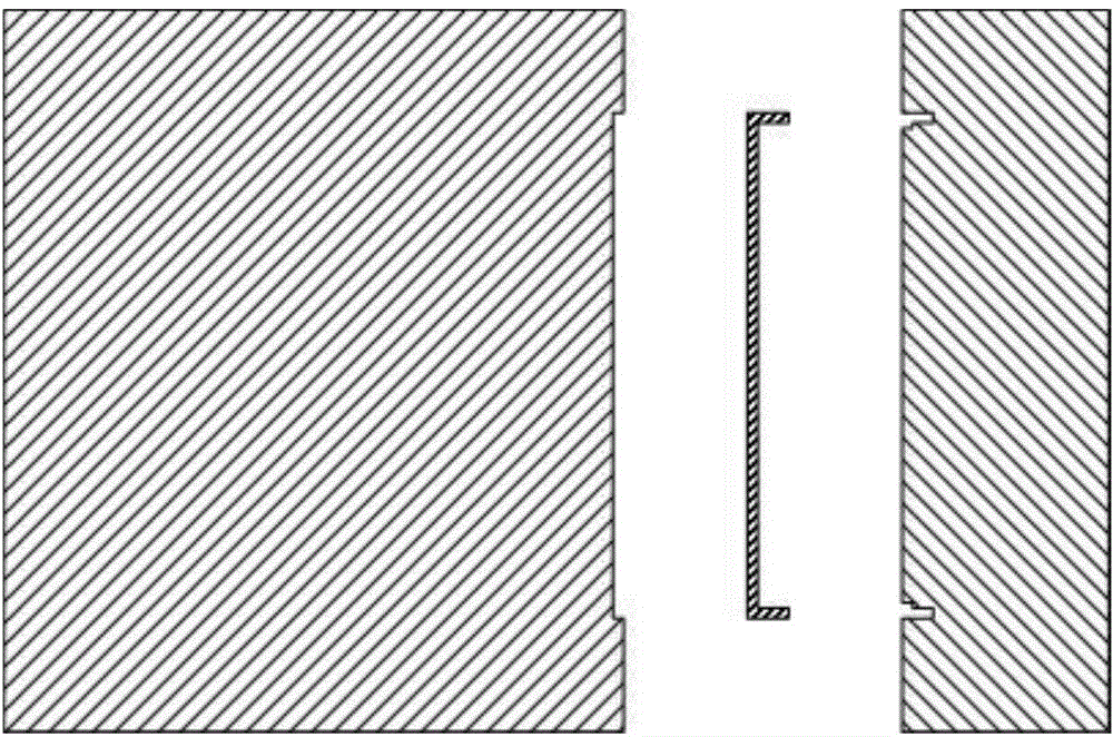
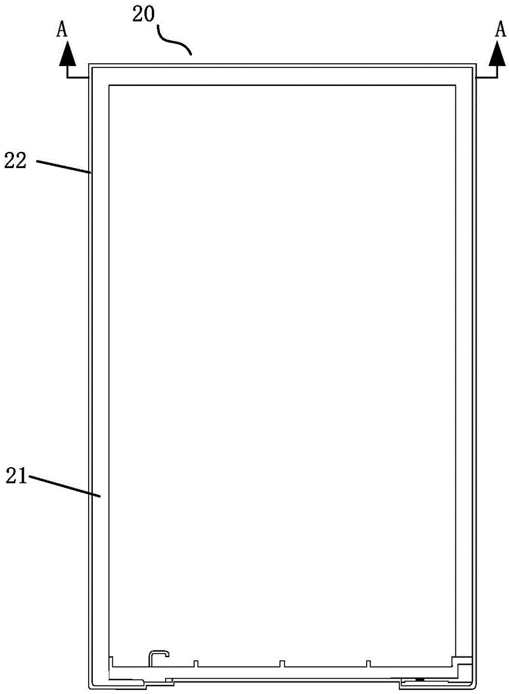
[0024] figure 2 It is a schematic diagram of the plastic-iron integrated frame structure, such as figure 2 As shown, in this embodiment, the plastic-iron integrated frame 20 includes a plastic frame 21 and an iron frame 22 , and the plastic frame 21 is arranged around the edge of the iron frame 22 .

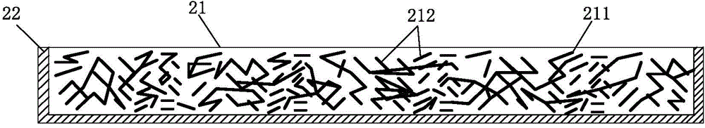
[0025] In this embodiment, the plastic frame is formed by mixed injection molding of plastic particles and solid additives, the material shrinkage rate of the solid additives is smaller than that of the plastic particles, and the melting point of the solid additives is higher than that of the solid additives. The melting point of the plastic particles, the plastic particles are mixed with the solid additives, so that the shrinkage rate of the plastic particles is reduced, and further, the plastic-iron integrated frame has little or no deformation after molding.

[0026] The melting point of the solid additive is greater than the maximum temperature of the injection molding pro...

Embodiment 2

[0038] Figure 4 It is a flow chart of the method for manufacturing the rubber-iron integrated frame provided by Embodiment 2 of the present invention, as shown in Figure 4 As shown, in this embodiment, the manufacturing method of the rubber-iron integrated frame provided by the present invention includes the following steps:

[0039] S401: Put the iron frame on the mold core of the injection mold for injection molding the plastic-iron integrated frame.

[0040] S402: Clamp the mold core, and inject plastic into the injection cavity formed by the iron frame and the mold core.

[0041] The mold core is molded together, the iron frame and the mold core form an injection cavity, and plastic is injected into the injection cavity to form a plastic frame. Plastics formed from injection molding compositions.

[0042] Further, specifically, the iron frame and the mold core form an injection cavity, and plastic is injected into the injection cavity to form a plastic frame. The plas...


PUM

PropertyMeasurementUnit
lengthaaaaaaaaaa

Abstract

The invention discloses an injection molding composition for a rubber and iron integrated frame, the rubber and iron integrated frame and a manufacture method of the rubber and iron integrated frame. The injection molding composition for the rubber and iron integrated frame comprises a plastic granule and a solid additive, wherein the shrinking percentage of the solid additive is less than that of the plastic granule; the solid additive comprises at least one of a glass fiber, a carbon fiber or a boron fiber; when injection molding is carried out, the plastic granule and the solid additive are mixed and injection molded, so that the using volume of the plastic granule is reduced, the injection amount of the plastic granule is reduced and the shrinking percentage of the injection molding plastic of the rubber and iron integrated frame is reduced; the melting point of the solid additive is higher than that of the plastic granule, the injection molding temperature is controlled between the melting points of the solid additive and the plastic granule. The solid additive is kept in a solid state in the injection molding process so that the deformation degree after shaping the rubber and iron integrated frame is small or none.

Description

technical field [0001] The invention relates to the field of backlight module processing, in particular to an injection molding composition for a rubber-iron integrated frame, a rubber-iron integrated frame and a manufacturing method thereof. Background technique [0002] With the gradual popularization of electronic liquid crystal display devices, consumers have higher and higher requirements for liquid crystal display products, not only requiring products to be thinner and thinner in appearance, but also hoping that the products can have certain guarantees in terms of quality and structural strength. However, when the backlight module in liquid crystal display products is designed with a narrow frame, the deformation problem of the rubber-iron integrated frame in the backlight module is often ignored. If the deformation of the backlight module is too large, the display effect of the liquid crystal display device will be seriously affected, and even the screen may burst. ...

Claims


Application Information

Patent Timeline
Patent Type & Authority Applications(China)
IPC IPC(8): C08L101/00C08K7/06C08K7/14B29C45/14G02F1/13357
Inventor 熊远江杨秀清
Owner SHENZHEN TECHASER TECH
Why Eureka
Try Eureka