Metal hydride hydrogen storage device

A hydrogen storage device and hydride technology, which is applied in fixed capacity gas storage tanks, gas/liquid distribution and storage, pressure vessels, etc., can solve uneven heat transfer, inability to obtain heat, uneven hydrogen release of hydrogen storage alloys, etc. problems, to achieve the effects of easy manufacturing and processing, improved hydrogen release performance, and increased heat exchange area

Inactive Publication Date: 2015-06-03
GENERAL RESEARCH INSTITUTE FOR NONFERROUS METALS BEIJNG
View PDF10 Cites 15 Cited by
  • Summary
  • Abstract
  • Description
  • Claims
  • Application Information

AI Technical Summary

Problems solved by technology

However, there are also deficiencies in the hydrogen storage of metal hydrides. For example, the dehydrogenation of metal hydrides is an endothermic process. If the heat exchange is insufficient, the temperature will drop rapidly, which will cause the metal hydrides to fail to desorb hydrogen quickly, making it impossible to meet the requirements of fuel cells.
The metal hydride hydrogen storage devices provided by patents CN2861702Y, CN1609499A, CN201562717U, and CN2658543Y etc. have square casing heat exchange fins outside the hydrogen storage tank, which increases the heat exchange area between the hydrogen storage tank and the environment and improves the heat exchange efficiency , but its biggest disadvantage is uneven heat exchange. The side of the hydrogen storage device facing the heat source can effectively obtain heat, but the other side cannot obtain heat, which will cause uneven temperatures on both sides of the hydrogen storage tank. The hydrogen storage alloy at different positions in the tank is not uniform in hydrogen release, which affects the hydrogen release performance of the hydrogen storage device

Method used


Image

  • Metal hydride hydrogen storage device
  • Metal hydride hydrogen storage device
  • Metal hydride hydrogen storage device

Examples


Embodiment Construction

[0020] The present invention will be described in further detail below in conjunction with the accompanying drawings and specific embodiments, but the present invention is not limited to the following embodiments.

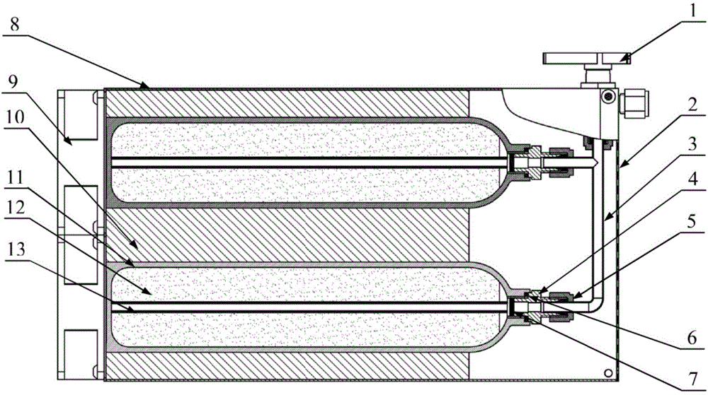
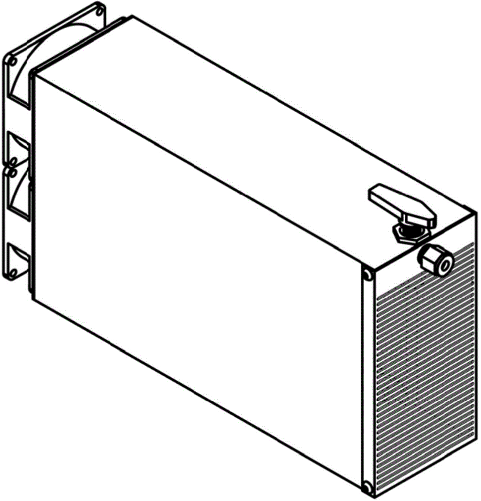
[0021] Such as figure 1 with figure 2 Shown are the structural schematic diagram (section view) and outline schematic diagram of the metal hydride hydrogen storage device provided by the present invention respectively. Gasket 6, filter sheet 7, shell 8, fan 9, longitudinal heat exchange finned tube 10, hydrogen storage bottle body 11, hydrogen storage material bed body 12, porous air duct 13;

[0022] One end of the bottle mouth joint 4 is connected and sealed with the hydrogen storage bottle body 11 through a sealing gasket 6, and the other end is connected with the gas pipe 3 through a ferrule 5; The valve 1 is connected; the front cover 2 is installed on the end of the shell 8 close to the valve 1, and two fans 9 are installed on the end away from the valve 1...


PUM


Abstract

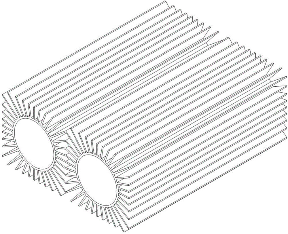
The invention discloses a metal hydride hydrogen storage device, which belongs to the technical field of hydrogen storage. The device is composed of a valve, a front cover, a gas path tube, a bottleneck connector, a clamping sleeve, a sealing gasket, a filter disc, a shell, two fans, a longitudinal heat transfer finned tube, a hydrogen storage container, a hydrogen storage material bed body, and a porous gas guide tube, wherein the bottleneck connector is connected with a hydrogen storage bottle body and the gas path tube by the sealing gasket and the clamping sleeve; the gas path tube is connected with the porous gas guide tube and the valve by the filter disc; the front cover and the two fans are arranged on the shell, and the longitudinal heat transfer finned tube and a hydrogen storage bottle are arranged in the shell; and the hydrogen storage material bed body and the porous gas guide tube are arranged in the hydrogen storage bottle body. The metal hydride hydrogen storage device disclosed by the invention is simple in structure, and easy to manufacture and process; and the longitudinal heat transfer finned tube can ensure the uniform heat transfer of the hydrogen storage container while the heat transfer efficiency of the hydrogen storage container is improved, so that the uniformity of hydrogen desorption of the hydrogen storage material bed body in the hydrogen storage container is ensured, and the hydrogen desorption performance is significantly improved.

Description

technical field [0001] The invention belongs to hydrogen storage technology in the field of hydrogen energy, in particular to a metal hydride hydrogen storage device. Background technique [0002] With the development of society, fossil fuels such as coal, oil, and natural gas can no longer meet the growing needs of human beings. At the same time, the use of fossil fuels has caused the deterioration of the ecological environment, such as the greenhouse effect. In addition, coal, oil, natural gas, etc. are non-renewable resources with limited reserves on the earth, and it is impossible for human beings to depend on them all the time. Therefore, many countries are researching and developing new alternative energy sources, such as wind energy, solar energy, hydrogen energy, nuclear energy, biomass energy, water energy, ocean energy, etc. The combustion calorific value of hydrogen is high, and the energy after burning per kilogram of hydrogen is about 3 times that of gasoline, ...

Claims


Application Information

Patent Timeline
Patent Type & Authority Applications(China)
IPC IPC(8): F17C1/00F17C13/00
CPCY02E60/32
Inventor 叶建华李志念刘晓鹏蒋利军王树茂袁宝龙郭秀梅赵旭山姬江峰邱昊辰
Owner GENERAL RESEARCH INSTITUTE FOR NONFERROUS METALS BEIJNG
Why Eureka
Try Eureka