Small-sized ultra-high-speed motor test loading device

A technology of motor testing and loading device, applied in measuring devices, power measurement, instruments, etc., can solve the problems of motor shafting vibration, shafting vibration, inability to carry out, etc., and achieves a small moment of inertia, no friction loss, and easy installation. Effect

Inactive Publication Date: 2015-06-10
王晛
View PDF15 Cites 10 Cited by
  • Summary
  • Abstract
  • Description
  • Claims
  • Application Information

AI Technical Summary

Problems solved by technology

However, in ultra-high-speed motors, the coaxiality error of the coupling installation will cause a lot of vibration and noise, which will affect the test accuracy. In some cases, the test cannot even be carried out because the small high-speed motor has a high speed and a small load torque. The inertia of the test device is small and the load torque is strictly coaxial with the high-speed motor. Otherwise, an asymmetric radial force will be generated on the motor shaft, which will cause shaft vibration and affect the test accuracy, and even damage the high-speed motor bearings.
The magnetic coupling can realize the non-contact power transmission between the motor and the dynamometer, but the mass of the magnetic coupling itself and the inhomogeneity of the air gap during installation will cause a large asymmetrical radial force, plus the non-negligible Dynamometer rotor friction loss, resulting in low detection accuracy
[0003] Chinese patent CN1211729A "Non-contact torque measuring device", Chinese patent CN104155038A "Non-contact electric saw machine power fast measurement method", use the excitation coil to generate a unipolar magnetic field in the air gap of the ferromagnetic material, the magnetic field and the eddy current Partial coupling of disks generates load torque and realizes non-contact loading. This structure is suitable for medium and low speed loads, but it is not suitable for small high-speed motors, because the torque generated by the eddy current disks in the above patents is unevenly distributed on the disks, which will make the The motor shaft produces asymmetrical radial force, which causes the vibration of the shaft system and affects the test accuracy
[0004] Chinese patent 101488691 "Variable air gap eddy current speed regulation induction motor and its working mode", Chinese patent CN10140042C "adjustable magnetic coupler" generates symmetrical load torque through eddy current disk and permanent disk or armature winding magnetic field induction, and realizes non-contact loading , but the structure must ensure that the air gap between the eddy current disk and the permanent disk or the stator core is uniform, otherwise the load torque will produce a large asymmetric distribution, which will cause the vibration of the motor shaft system. The coaxiality puts forward very high requirements, and it is easier to realize the project for medium and low speed occasions, but it is difficult to realize it for high-speed motors

Method used


Image

  • Small-sized ultra-high-speed motor test loading device
  • Small-sized ultra-high-speed motor test loading device

Examples


Embodiment Construction

[0022] The present invention will be further described below in conjunction with the accompanying drawings and embodiments.

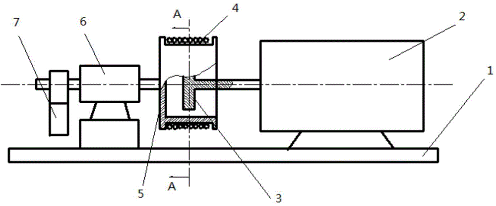
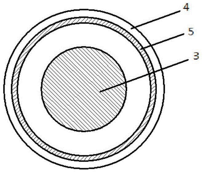
[0023] Such as figure 1 As shown, it is mainly composed of a high-speed rotating eddy current disk 3, a stationary excitation sleeve 5 and a torque detection system. When in use, the eddy current disk 3 is coaxially connected with the output shaft of the motor 2, and the excitation winding 4 of the excitation sleeve 5 is connected to an adjustable DC power supply. The induced current in the disk generates braking torque, the magnitude of which is monitored and displayed by the torque detection system, combined with the speed detection to obtain the load power. Adjusting the excitation current can easily adjust the load power.

[0024] Such as figure 1 As shown, the eddy current disk 3 is made of non-magnetic conductive materials, such as copper, aluminum, stainless steel, etc., which can reduce the axial force on the motor. The eddy current disk and ...


PUM


Abstract

The invention discloses a small-sized ultra-high-speed motor test loading device which comprises a base, a motor, an eddy-current disc, an exciting winding, an exciting sleeve, a support and a dynamometer load. The motor is arranged on the base and is connected with the eddy-current disc, the eddy-current disc is nested in the exciting sleeve, the eddy-current disc and the exciting sleeve are coaxially and parallelly arranged and transfer power through magnetic field coupling, the exciting sleeve is winded with the exciting winding, the exciting winding is connected with a voltage-adjustable direct-current power supply to produce exciting current, the exciting current produces an even unipolar magnetic field in the exciting sleeve, the magnetic field senses current in the rotary eddy-current disc to produce brake torque, a torque measurement system measures the brake torque, and the small-sized ultra-high-speed motor test loading device is provided with a rotation speed detection system for measuring the rotation speed of the motor or the eddy-current disc. The small-sized ultra-high-speed motor test loading device is simple in structure, small in rotational inertia, almost free of additional radial force, convenient to install and capable of reducing vibration and noise and is suitable for performance testing of small-sized high-speed motors, and a dynamometer rotor is free of friction loss.

Description

technical field [0001] The invention relates to a small ultra-high-speed motor test loading device. Background technique [0002] In the performance test of the motor, various dynamometers are widely used as loads. There are many types of dynamometers, mainly including hysteresis dynamometers, eddy current dynamometers, magnetic powder dynamometers, and synchronous dynamometers. In the conventional motor test, the motor and the dynamometer are generally rigidly connected by a mechanical coupling to realize power transmission. However, in ultra-high-speed motors, the coaxiality error of the coupling installation will cause a lot of vibration and noise, which will affect the test accuracy. In some cases, the test cannot even be carried out because the small high-speed motor has a high speed and a small load torque. The inertia of the test device is small and the load torque is strictly coaxial with the high-speed motor. Otherwise, an asymmetric radial force will be generated ...

Claims


Application Information

Patent Timeline
Patent Type & Authority Applications(China)
IPC IPC(8): G01L3/22
Inventor 王晛王兴华李光友
Owner 王晛
Why Eureka
Try Eureka