A carbon-free membrane electrode assembly

A technology of carbon film electrodes and components, applied in the direction of electrical components, battery electrodes, circuits, etc., can solve the problems of reducing the electrochemical performance and stability of batteries, not nano-ordered structures, etc., to solve the problem of carbon corrosion and improve operation stability Sexuality and longevity, performance-enhancing effects

Active Publication Date: 2015-06-10
SHANGHAI ADVANCED RES INST CHINESE ACADEMY OF SCI
View PDF18 Cites 6 Cited by
  • Summary
  • Abstract
  • Description
  • Claims
  • Application Information

AI Technical Summary

Problems solved by technology

[0012] It can be seen that these patented designs only involve the preparation of the catalytic layer, and there are still some challenges: either the nano-ordered structure is not

Method used


Image

  • A carbon-free membrane electrode assembly
  • A carbon-free membrane electrode assembly
  • A carbon-free membrane electrode assembly

Examples


Embodiment 1

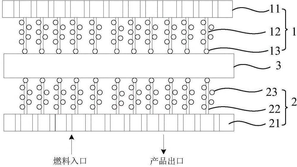
[0049] The present invention provides a carbon-free membrane electrode assembly, which at least includes: a cathode membrane electrode 1 , an anode membrane electrode 2 and a solid polymer dielectric membrane 3 .

[0050] Wherein, the cathode membrane electrode 1 includes a porous and conductive cathode current collecting plate 11, a cathode ordered nano-array 12 grown on the surface of the cathode current collecting plate 11, and a cathode combined on the upper surface of the cathode ordered nano-array 12. Catalyst layer 13.

[0051] In an application example, the cathode current collector 11 is made of a porous conductive material. Porous, for the transport of reactants, products, and electrons, can be used as fuel inlet and product outlet; conductive, for the output of current. The cathode current collector 11 is one of porous titanium, porous stainless steel, aluminum oxide, and conductive polymer, or a composite material of at least two of the above. In this embodiment,...

Embodiment 2

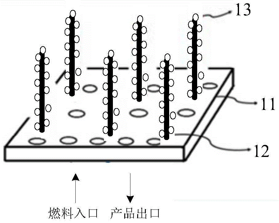
[0061] see figure 2 , is shown as a simplified structural schematic diagram of an embodiment of the carbon-free membrane electrode assembly of the present invention. For the sake of simplicity, the anode membrane electrode and the cathode membrane electrode have the same structure, which is not shown in the figure; the anode membrane electrode and the cathode membrane electrode have the same structure. The solid polymer electrolyte membrane between the membrane electrode structures is also omitted, and only the cathode membrane electrode assembly is shown.

[0062] In this embodiment, the cathode current collecting plate 11 is a porous titanium plate; the nano-ordered array 12 is an ordered array of polypyrrole nanowires.

[0063] The specific process steps are as follows:

[0064] (1) Pretreatment of porous titanium plate:

[0065] In order to provide enough nucleation sites, activate the core center, reduce the interfacial energy resistance, and facilitate the vertical gr...

Embodiment 3

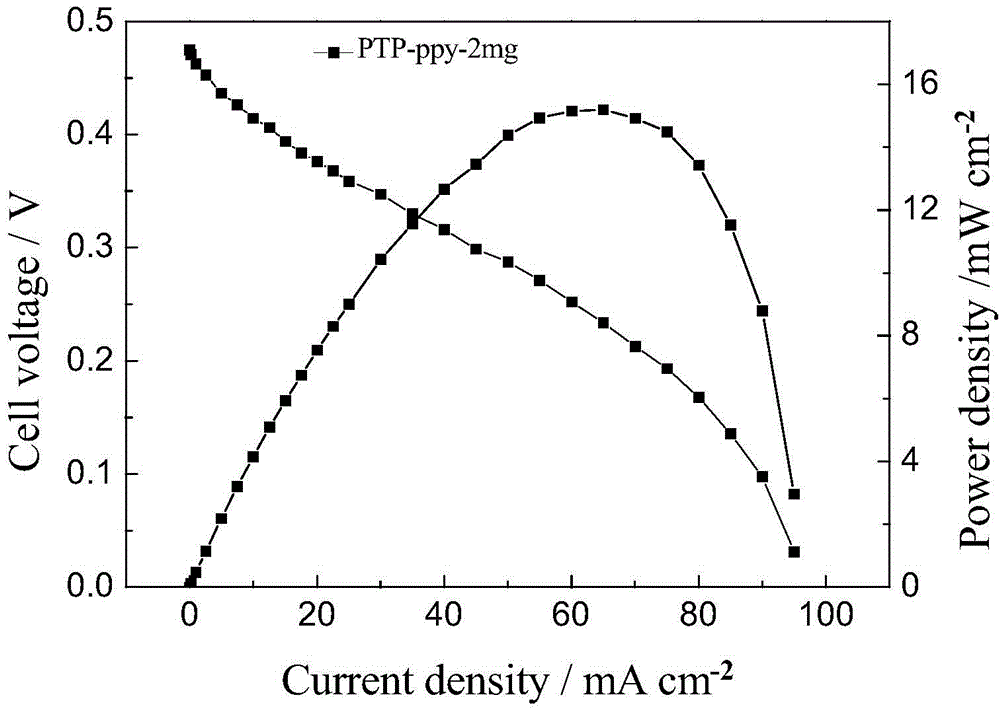
[0075] The preparation method of this example is the same as that of Example 2. The porous titanium plate is used as the substrate, that is, the cathode current collecting plate 11, and nanometer-ordered polypyrrole nanometers are grown on the surface of the porous titanium plate by electropolymerization. Tube array 12, then use the porous titanium plate as an electrode, the electrolyte is a mixed solution of chloroplatinic acid and ruthenium chloride, and -0.25Vvs saturated calomel is a reference electrode, in the polypyrrole ordered nanotube array In-situ deposition on the surface generates a load of 0.2 mg.cm -2 The PtRu alloy catalyst, that is, the cathode catalytic layer 13, the ratio of Pt atoms and Ru atoms is 3:1.

[0076] It should be noted that, for the sake of simplicity, the structure of the anode membrane electrode and the cathode membrane electrode is the same, which is not shown in the figure; the solid polymer electrolyte membrane between the structure of the a...


PUM

PropertyMeasurementUnit
Apertureaaaaaaaaaa

Abstract

A carbon-free membrane electrode assembly is provided. The carbon-free membrane electrode assembly at least comprises a cathode membrane electrode, an anode membrane electrode and a solid polymer electrolyte membrane used for conducting protons, wherein the cathode membrane electrode at least comprises a porous and electrically-conducting cathode collector plate, a cathode nano-ordered array grown on the surface of the cathode collector plate and a cathode catalytic layer combined on the surface of the cathode nano-ordered array; and the anode membrane electrode at least comprises a porous and electrically-conducting anode collector plate, an anode nano-ordered array grown on the surface of the anode collector plate and an anode catalytic layer combined on the surface of the anode nano-ordered array. The assembly adopts the nano-ordered arrays as carriers for the catalytic layers so that the utilization rate of a catalyst is close to 100%, thus largely improving performance of the catalytic layers. The membrane electrodes are carbon-free, thus facilitating complete solving of a carbon corrosion problem in a fuel cell, thereby largely improving running stability and prolonging the service lifetime of the cell.

Description

technical field [0001] The invention relates to a fuel cell, in particular to a carbon-free membrane electrode assembly in which a catalyst layer with an ordered nanostructure is grown controllably on the surface of a microporous collector plate. Background technique [0002] A fuel cell is an energy conversion device that directly converts the chemical energy stored in the fuel into electrical energy without being limited by the Carnot cycle. It is one of the popular candidates for power sources because of its high energy conversion efficiency. The solid polymer fuel cell is very suitable for use as a mobile power source for electric vehicles and various portable electronic products (such as mobile phones, notebooks, handheld electronic devices, etc.). High performance, high reliability and low cost are the keys to realize its commercial application. [0003] Solid polymer fuel cells mainly include proton exchange membrane fuel cells and direct alcohol fuel cells. The anod...

Claims


Application Information

Patent Timeline
IPC IPC(8): H01M4/86H01M8/10H01M4/90
CPCY02E60/50
Inventor 张海峰武慧娟郭静蒋晶晶邹志青杨辉
Owner SHANGHAI ADVANCED RES INST CHINESE ACADEMY OF SCI
Why Eureka
Try Eureka