Micro transceiver assembly

A transceiver and unit technology, applied in the field of miniaturized transceiver components, can solve the problems of unsuitable miniaturized and miniaturized microwave radio frequency circuits, complex circuit design, low gain, etc., and achieve good circuit consistency and high gain , the effect of suppressing interference

Active Publication Date: 2015-06-10
庄昆杰
View PDF5 Cites 5 Cited by
  • Summary
  • Abstract
  • Description
  • Claims
  • Application Information

AI Technical Summary

Problems solved by technology

[0004] In the process of realizing the present invention, the inventors found that there are at least the following problems in the prior art: the existing transceiver components are all realized by thick film technology, the circuit design is complicated, the cost is high, and the gain is low and the noise is large, which is not suitable for Miniaturized and miniaturized microwave radio frequency circuit

Method used


Image

  • Micro transceiver assembly
  • Micro transceiver assembly
  • Micro transceiver assembly

Examples


Embodiment 1

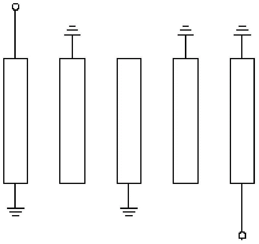
[0049] In the first embodiment, the miniaturized transceiver components are fabricated on the ceramic substrate by adopting ultra-fine microstrip thin film technology, and the ceramic substrate is specifically selected from an aluminum oxide ceramic substrate with a dielectric constant of 9.9 and a thickness of 0.5 mm. The overall structural layout of the miniaturized transceiver assembly can be found in Figure 5 , where the board with holes is the ground plane, see Figure 5 shown. Each part is described in detail below.

[0050] In Embodiment 1, the structural diagram of the balanced amplifier can be found in Figure 6 As shown, the miniaturized transceiver assembly provided by Embodiment 1 has four balanced amplifiers in total. Figure 5 Only the first balanced amplifier CP1 is marked in .

[0051] Wherein, in the first embodiment, the first 3dB quadrature bridge and the second 3dB quadrature bridge in the balanced amplifier are both S-shaped curved Lange bridges, and ...


PUM


Abstract

The invention discloses a micro transceiver assembly. The micro transceiver assembly comprises an AGC (automatic gain control) receiving module and an ALC (adaptive logic circuit) emitting module, wherein the AGC receiving module comprises a first balance amplifier, a first micro belt filter, a first electrically controlled attenuator, a second balance amplifier, a first coupler and a first direct-current processing circuit; the ALG emitting module comprises a second electrically controlled attenuator, a third balance amplifier, a second micro belt filter, a fourth balance amplifier, a second coupler and a second direct-current processing circuit; the first balance amplifier, the second balance amplifier, the third balance amplifier, the fourth balance amplifier, the first micro belt filter, the second micro belt filter, the first electrically controlled attenuator, the second electrically controlled attenuator, the first coupler and the second coupler are manufactured on a ceramic base plate through a superfine micro belt film process. The micro transceiver assembly is integrated on a circuit in the form of a distribution parameter, so that peripheral assemblies are reduced, the integration degree of the whole transceiver assembly is relatively high and the size of the transceiver is greatly reduced.

Description

technical field [0001] The invention relates to the technical field of mobile communication, in particular to a miniaturized transceiver assembly. Background technique [0002] When the receiver receives a signal, the signal level at its input may vary in a wide range, and the output power of the receiver varies with the size of the external signal, so the output of the receiver will have a very different strength. signal power. If it is necessary to maintain the linear amplification of the receiving equipment in such a wide range without saturation and distortion of the signal, it is necessary to control the gain of the receiver to keep the output signal at an appropriate level to ensure the normal operation of the receiver. And through an AGC (Automatic Gain Control, automatic gain control) circuit, the gain of the amplifying circuit can be automatically adjusted according to the signal strength. The AGC circuit adjusts the output signal using an effective combination of...

Claims


Application Information

Patent Timeline
Patent Type & Authority Applications(China)
IPC IPC(8): H04B1/40
Inventor 庄昆杰
Owner 庄昆杰
Why Eureka
Try Eureka