
Rapid drying treatment equipment for garbage

A kind of processing equipment and fast technology, applied in the direction of garbage drying, lighting and heating equipment, drying, etc., can solve the problems of secondary pollution, serious secondary pollution, long cycle, etc., to reduce labor intensity and achieve the effect of automatic control

Inactive Publication Date: 2015-06-17
QINGDAO WATER WORLD ENVIRONMENTAL PROTECTION TECH
View PDF0 Cites 2 Cited by
  • Summary
  • Abstract
  • Description
  • Claims
  • Application Information

AI Technical Summary

Problems solved by technology

[0004] 1. Mixed and received ingredients are complicated, and the content of bags is high;
[0005] 2. High water content, the average water content is 50%, and the limit water content is as high as 70%;
[0006] 3. The content of kitchen waste and muck is high, and it is difficult to separate and dehydrate;
[0007] 4. The content of perishable substances is high, and improper handling will cause serious secondary pollution
[0011] 1. The operating environment is harsh and the secondary pollution is serious: the method of draining water and fermentation and evaporation is used to remove water, which has a long cycle, a large amount of malodorous gas emissions, a large amount of landfill leachate, and high COD and BOD content in the leachate. Treatment costs are high ;
[0012] 2. Affected by the change of garbage moisture, the performance of fermentation products is extremely unstable

Method used


Image

  • Rapid drying treatment equipment for garbage
  • Rapid drying treatment equipment for garbage
  • Rapid drying treatment equipment for garbage

Examples


Embodiment Construction

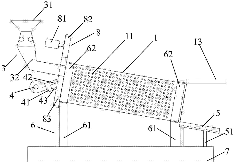
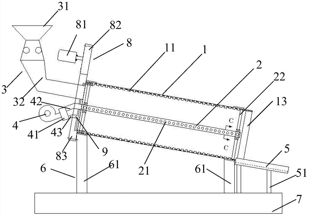
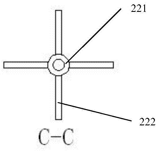
[0049] figure 1 and figure 2 Respectively show the garbage quick drying treatment equipment of the present invention, Figure 4 Shows the schematic diagram of the circuit used to control the automatic water removal of garbage in the present invention, as figure 1 , figure 2 and Figure 4 As shown, the garbage quick-drying treatment equipment includes: a drum 1 with a plurality of water outlet holes 11 distributed thereon; The air outlet 21 of 11; The feeding device 3 that communicates with the inlet 12 of the drum 1; The air supply device connected to one end of the radial blow pipe 2; Connect the air supply device and align with the axial direction of the front end of the drum 1 The blowing pipe 9; the driving device 8 used to drive the rotation of the drum 1; the electric hatch 13 installed at the outlet of the drum 1 to open or close the outlet of the drum; connect the air supply device, the driving device 8 and the electric motor respectively. The controller of the ...


PUM


Abstract

The invention discloses rapid drying treatment equipment for garbage. The rapid drying treatment equipment comprises a roller with a plurality of water outlets distributed, a radial blowing pipe, an air supply device, an axial blowing pipe, a driving device, an electric cabin door and a controller. The radial blowing pipe is mounted in the roller, and a plurality of air outlets facing water outlets are formed in the radial blowing pipe; the air supply device is connected with one end of the radial blowing pipe; the axial blowing pipe is connected with the air supply device and is aligned at the front end of the roller; the driving device is used for driving the roller to rotate, and the electric cabin door is mounted on an outlet of the roller and used for opening or closing the outlet of the roller; the controller is connected with the air supply device, the driving device and the electric cabin door and used for controlling the air supplying device to supply air to the radial blowing pipe and the axial blowing pipe respectively, controlling the electric cabin door to open or close the outlet of the roller and controlling the roller to rotate; and the other end of the radial blowing pipe is a closed end, and an air inlet of the air supply device is connected with a hot air outlet of a garage incinerator through a pipeline. According to the equipment, spinning drying and hot air drying treatment can be carried out on garbage at the same time, and automatic control over water removing treatment of the garbage is achieved.

Description

technical field [0001] The invention relates to the technical field of environmental protection, in particular to a rapid drying treatment equipment for garbage. Background technique [0002] At present, our country's municipal solid waste is increasing at a rate of 10% every year, while the simple treatment of urban waste only accounts for 2.3% of the total. At present, the area of ​​arable land occupied by our country's garbage stockpiles over the years is about 500 million square meters, and the direct economic loss is as high as 8 billion yuan. The number of cities across the country has grown to 660, and 200 of them have been surrounded by garbage. Based on an urban population of 260 million and each person producing 440 kg of waste per year, the amount of waste generated is 114 million tons, which can cover a city with a population of 1 million by 1 meter. And it is still increasing at a rate of 8-10% every year. China has become the country with the heaviest burden...

Claims


Application Information

Patent Timeline
IPC IPC(8): F23G5/04B09B3/00B09B5/00B07B7/00
CPCF26B11/04F26B7/00F26B21/00F26B25/00F26B25/16F26B2200/04
Inventor 童乐张光辉
Owner QINGDAO WATER WORLD ENVIRONMENTAL PROTECTION TECH
Learn More