Photovoltaic cell module and manufacturing method thereof

A photovoltaic cell and manufacturing method technology, applied in photovoltaic power generation, circuits, electrical components, etc., can solve problems such as affecting the appearance and reliability of photovoltaic modules, high long-term stability, and breaking welding joints, so as to improve long-term stability, The effect of improving performance and reducing corrosion requirements

Active Publication Date: 2015-06-17
常州市异质结管理咨询合伙企业(有限合伙)
View PDF6 Cites 20 Cited by
  • Summary
  • Abstract
  • Description
  • Claims
  • Application Information

AI Technical Summary

Problems solved by technology

Our experiment found that during the lamination process, EVA will push the round fine interconnection wire upwards away from the surface of the battery along the arc surface of the lower part of the round fine interconnection wire, which may break the soldering point, thus affecting the appearance an

Method used


Image

  • Photovoltaic cell module and manufacturing method thereof
  • Photovoltaic cell module and manufacturing method thereof
  • Photovoltaic cell module and manufacturing method thereof

Examples


Embodiment 1

[0046] Embodiment 1: For the embodiment of a conventional P-type battery, Cu interconnection wires and heat-curable Cu conductive paste are used.

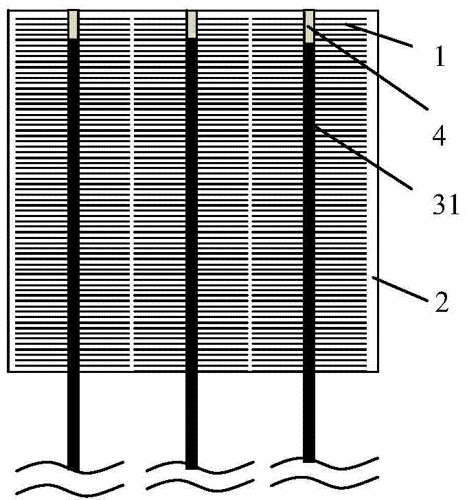
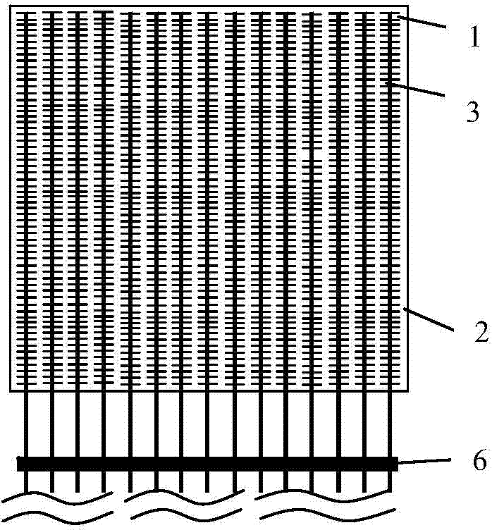
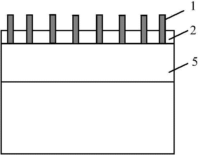
[0047] 15 thin Cu wires are selected as interconnection wires 31 between the battery slices, the cross section of the thin Cu wires is square, and the side length of the square is 0.3 mm. The surface of the thin Cu wire is not coated with Sn layer.

[0048] Coating heat curing type Cu conductive paste on the surface of thin Cu wire. The solid content of heat-curable Cu conductive paste is 60-90%, and the density is 3.5-6g / cm 3 . Coating thickness is about 5um.

[0049] The fine Cu wire is straightened by a traction mechanism, and the heat-curable Cu conductive paste is coated on the fine Cu wire by a roller brushing method. The area where the heat-curable Cu conductive paste is coated on the fine Cu wire is limited to the area that needs to be connected to the battery sheet, and the heat-curable Cu conductive paste is not coate...

Embodiment 2

[0054] Embodiment 2: For the embodiment of thin-film silicon / crystalline silicon heterojunction cells, Cu interconnection wires and heat-curable Cu conductive paste are used.

[0055] 15 thin Cu wires are selected as interconnection wires 31 between the battery slices, the cross section of the thin Cu wires is square, and the side length of the square is 0.3 mm. The surface of the thin Cu wire is not coated with Sn layer.

[0056] Coating heat curing type Cu conductive paste on the surface of thin Cu wire. The solid content of heat-curable Cu conductive paste is 60-90%, and the density is 3.5-6g / cm 3 . Coating thickness is about 5um.

[0057] The fine Cu wire is straightened by a traction mechanism, and the heat-curable Cu conductive paste is coated on the fine Cu wire by a roller brushing method. The area where the heat-curable Cu conductive paste is coated on the fine Cu wire is limited to the area that needs to be connected to the battery sheet, and the heat-curable Cu ...

Embodiment 3

[0062] Embodiment 3: For the embodiment of thin-film silicon / crystalline silicon heterojunction cells, Cu interconnection wires and heat-curable Ag conductive paste are used. Same as the other descriptions of Example 2, only the low-temperature-curing heat-curable Cu conductive paste was replaced by the low-temperature-curable heat-curable Ag conductive paste commonly used in the photovoltaic cell industry.


PUM

PropertyMeasurementUnit
Widthaaaaaaaaaa
Heightaaaaaaaaaa
Thicknessaaaaaaaaaa

Abstract

The invention relates to a photovoltaic cell module and a manufacturing method thereof. An interconnection lead wire of the photovoltaic cell module is connected with a thin grid line and a function ceramic thin film through cured type conducting slurry. According to the manufacturing method of the photovoltaic cell module, the interconnection lead wire coated with the cured type conducting slurry is attached to the surface of a cell piece in a pressing mode, and then curing is carried out; or the cured type conducting slurry is printed on the surface of the cell piece, then the interconnection lead is attached to the cured type conducting slurry in a pressing mode, and connecting of the thin grid line, the function ceramic thin film and the interconnection lead wire is achieved by curing; or a main grid line formed by curing of the cured type conducting slurry is arranged on the surface of the cell piece of the photovoltaic cell module. The photovoltaic cell module and the manufacturing method thereof have the advantages that the interconnection lead wire does not need to be connected with the cell piece through the high-temperature-sintered traditional main grid line, so that the processing step can be well simplified, and the performance of the cell piece is improved; and scaling powder and a protecting thin film are of no need, and the long-time stability of a component is improved.

Description

technical field [0001] The invention relates to a photovoltaic cell module and a manufacturing method thereof. Background technique [0002] At present, most manufacturers of photovoltaic cells and components in the industry adopt a battery electrode design and interconnection method of 2 to 5 bus bars. First, in the manufacturing process of photovoltaic cells, about 55 to 90 thin grid lines with a width of 60 to 100 um are formed on the front of a cell by screen printing and high temperature sintering. These thin grid lines are generally connected together by two 1.8mm main grid lines. Then, in the manufacturing process of the photovoltaic module, the busbars of the cells are electrically connected together with the copper interconnection wires coated with Sn layer through a high temperature (~200° C.) welding process. The photo-generated current on the surface of the battery collected by the thin grid line is collected on the main grid line, and then transferred to the S...

Claims


Application Information

Patent Timeline
IPC IPC(8): H01L31/05H01L31/18H01L31/0224
CPCY02E10/50
Inventor 黄强陈华
Owner 常州市异质结管理咨询合伙企业(有限合伙)
Why Eureka
Try Eureka