Ultrasonic separation device for fine particles

A separation device and fine particle technology, applied in the field of physical separation equipment research, can solve the problems of unsatisfactory effect, huge equipment, long separation time, etc., and achieve the effect of shortening equipment cost, shortening processing time, and compact equipment structure

Inactive Publication Date: 2015-06-24
SHAANXI NORMAL UNIV
View PDF5 Cites 25 Cited by
  • Summary
  • Abstract
  • Description
  • Claims
  • Application Information

AI Technical Summary

Problems solved by technology

[0002] For the fine particle pollutants produced in various production processes, the traditional method is to use ceramic filter adsorption, fine bubble adsorption, and natural precipitation using the density difference between the fluid and fine inclusions to remove them. There are also methods such as electric field ] Or the technology of magnetic field to remove tiny inclusions in the fluid. But when the particle size of the particles is less than 60μm, the effect of these technologies is not ideal. With the development of ultrasonic technology, ultrasonic waves are used to remove particles, air bubbles or The new method of liquid droplets has been paid more and more attention by people. However, the current researchers basically use the method of standing wave or traveling wave to separate the tiny particles in the fluid. The traditional ultrasonic separation of fine particles uses the particles in the antinode or Acoustic pressure nodes gather to form larger particles and finally settle down under the action of gravity, and the condition must be that the number of fine particles in the fluid is large, so that the fine particles have the opportunity to collide and gather to form large agglomerates of particles to settle down
However, when the number of fine particles in the fluid is small, the chance of collision will be reduced, and the number of large agglomerates formed by aggregation will be very small, so that there are still fine particles suspended in the fluid, and even fine particles can finally aggregate. However, the separation time is also very long, and the entire processing device is huge. Therefore, theory and experiments have proved that it is difficult to separate particles in a short period of time by simple standing waves or traveling waves, and the equipment is relatively large. , resulting in high costs, high maintenance costs, and high energy consumption

Method used


Image

  • Ultrasonic separation device for fine particles
  • Ultrasonic separation device for fine particles

Examples


Embodiment 1

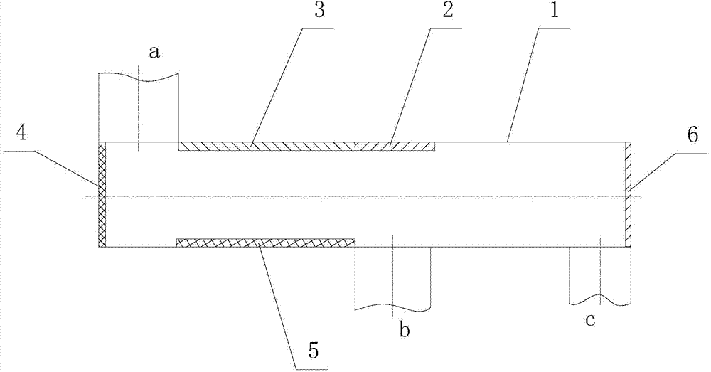
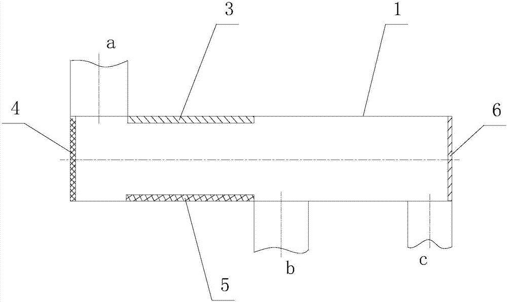
[0015] Depend on figure 1 It can be seen that the ultrasonic separation device of the fine particles of the present embodiment is composed of a dynamic separation chamber 1, a first ultrasonic transducer 3, a second ultrasonic transducer 6, a sound-absorbing plate 4, a reflecting plate 5 and a third ultrasonic transducer 2 composition.

[0016] The dynamic separation chamber 1 of the present embodiment is 40 mm high, 1600 mm long, 210 mm wide, and has a square cross-section. A water inlet a is processed at the top of the left end, and a water outlet c is processed at the bottom of the right end. The front end of c is processed with particle outlet b. On the top wall of water inlet a, 22 outlets with a frequency of 40KHz and an energy density of 12J / m are installed side by side. 3 The first ultrasonic transducer 3, the first ultrasonic transducer 3 is a piezoelectric transducer, its sound wave direction is perpendicular to the water flow direction, its total length is 1300mm, ...

Embodiment 2

[0019] The dynamic separation chamber 1 of the present embodiment is 75mm high, 2100mm long, and 210mm wide. The front end of c is processed with particle outlet b, and on the top wall of water inlet a, 32 outlets with a frequency of 20KHz and an energy density of 12J / m are installed side by side. 3 The first ultrasonic transducer 3, the first ultrasonic transducer 3 is a piezoelectric transducer, its sound wave direction is perpendicular to the water flow direction, its total length is 1800mm, the radiation surface of each first ultrasonic transducer 3 The diameter is 100mm, the distance between the first adjacent ultrasonic transducers 3 is 10mm, and the processing time is about 49s. A reflection plate 5 is installed at the bottom of the dynamic separation chamber 1 at the front end of the particle outlet b. The reflection plate 5 The length is 1800mm, the width is 210mm, and the thickness is 2mm. It is a flat plate made of stainless steel material. The distance between the ...

Embodiment 3

[0022] In this embodiment, the dynamic separation chamber 1 is 30mm high, 1980mm long, 210mm wide, and has a square cross-section. A water inlet a is processed on the top of the left end, and a water outlet c is processed on the bottom of the right end. The front end of the water inlet c is processed with a particle outlet b, and on the top wall of the water inlet a, there are 30 parallel installations with a frequency of 50KHz and an energy density of 12J / m 3 The first ultrasonic transducer 3, the first ultrasonic transducer 3 is a piezoelectric transducer, its sound wave direction is perpendicular to the water flow direction, its total length is 1680mm, the radiation surface of each first ultrasonic transducer 3 The diameter is 100mm, the distance between the first adjacent ultrasonic transducers 3 is 10mm, and the processing time is about 48s. A reflector 5 is installed at the bottom of the dynamic separation chamber 1 at the front end of the particle outlet b. The reflector...


PUM

PropertyMeasurementUnit
energy densityaaaaaaaaaa
thicknessaaaaaaaaaa

Abstract

The invention relates to an ultrasonic separation device for fine particles. The ultrasonic separation device is characterized in that a water inlet is formed in the top of a dynamic separation chamber, and a particle outlet and a water outlet are sequentially formed in the bottom of one end, opposite to the water inlet, of the dynamic separation chamber; a reflection plate is horizontally arranged at the front end of the particle outlet; a first ultrasonic transducer is arranged at the position, directly facing the reflection plate, on the top of the dynamic separation chamber; a second ultrasonic transducer is arranged at the water outlet of the dynamic separation chamber; an acoustic panel is arranged at the position, directly facing the second ultrasonic transducer, at the water inlet of the dynamic separation chamber. According to the ultrasonic separation device, by virtue of a low-frequency standing wave and high-frequency traveling wave combination method, the processing time is greatly shortened, the equipment cost is greatly lowered, the whole structure is compact, the fine particles, even a very limited number of fine particles in a flow field can be separated, furthermore, the separation time is short, and the separation effect is good.

Description

technical field [0001] The invention belongs to the technical field of physical separation equipment research, and in particular relates to an ultrasonic separation device for separating fine particles suspended in a fluid by means of ultrasonic waves. Background technique [0002] For the fine particle pollutants produced in various production processes, the traditional method is to use ceramic filter adsorption, fine bubble adsorption, and natural precipitation using the density difference between the fluid and fine inclusions to remove them. There are also methods such as electric field ] Or the technology of magnetic field to remove tiny inclusions in the fluid. But when the particle size of the particles is less than 60μm, the effect of these technologies is not ideal. With the development of ultrasonic technology, ultrasonic waves are used to remove particles, air bubbles or The new method of liquid droplets has been paid more and more attention by people. However, the...

Claims


Application Information

Patent Timeline
Patent Type & Authority Applications(China)
IPC IPC(8): B01D21/28C02F1/36
Inventor 班效强沈壮志于显涛
Owner SHAANXI NORMAL UNIV
Why Eureka
Try Eureka