Chirped pulse velocity interferometer

A technology of chirped pulses and interferometers, applied in the use of devices that measure the time required to move a certain distance, the re-radiation of electromagnetic waves, and the use of re-radiation, etc., can solve the problems of limiting the application range of the system and the high construction cost of VISAR , to achieve the effect of obvious price advantage and control of construction cost

Inactive Publication Date: 2015-06-24
LASER FUSION RES CENT CHINA ACAD OF ENG PHYSICS
View PDF9 Cites 14 Cited by
  • Summary
  • Abstract
  • Description
  • Claims
  • Application Information

AI Technical Summary

Problems solved by technology

However, the expensive price of the streak camera keeps the construction c

Method used


Image

  • Chirped pulse velocity interferometer
  • Chirped pulse velocity interferometer
  • Chirped pulse velocity interferometer

Examples


Embodiment 1

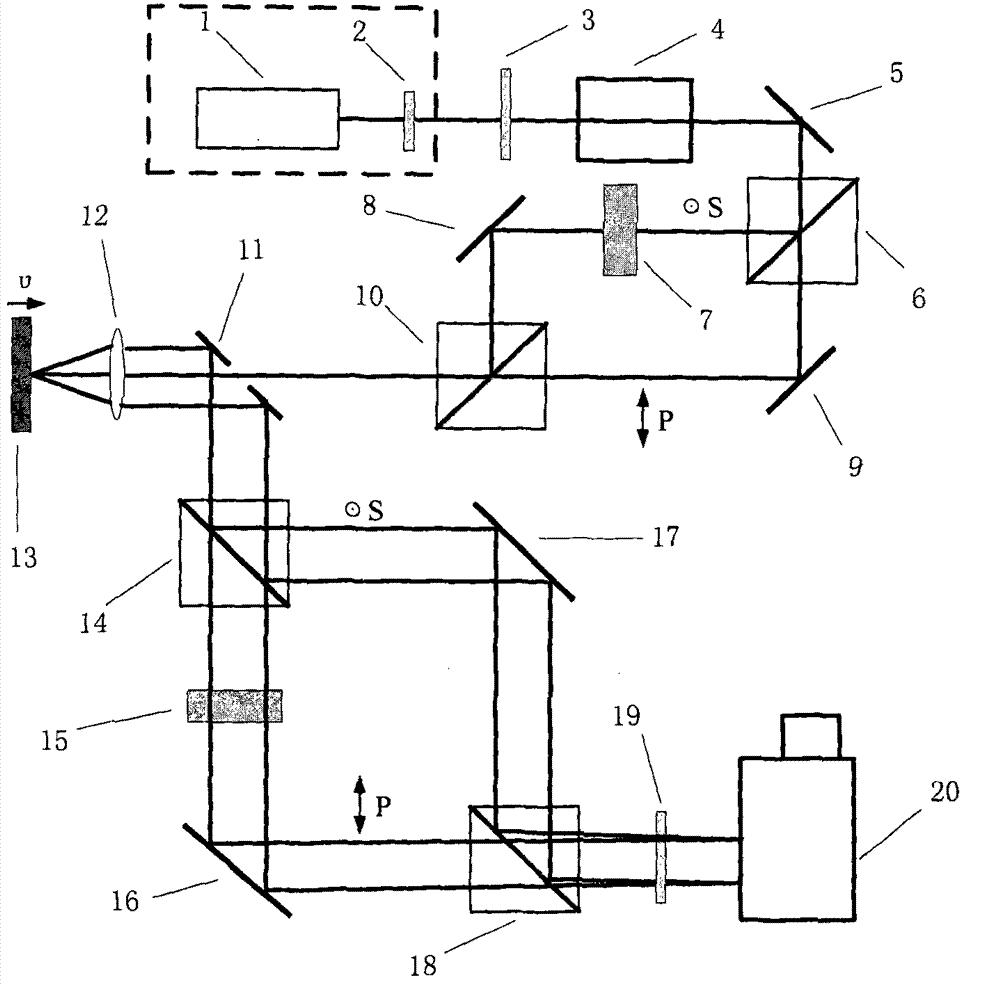
[0033] figure 1Shown, a kind of chirped pulse velocity interferometer of the present invention, supercontinuum pulse laser 1 outputs the supercontinuum laser pulse of certain central wavelength, filters into the laser pulse of required bandwidth after passing through broadband filter 2, utilizes polarizer again 3 and pulse stretcher 4 to change it into a linearly polarized linearly chirped pulse. After the chirped pulse passes through the reflector 5, it is divided into S-polarized light and P-polarized light by the polarization beam splitter 6 with the polarization directions perpendicular to each other, wherein the S-polarized light reaches the polarization beam-splitter prism 10 through the time delay device 7 and the mirror 8, and the P-polarized light After the light is reflected by the mirror 9, it is combined with the S-polarized light through the polarization beam splitter 10, and the time delay device 7 makes the combined S-polarized light lag behind the P-polarized l...

Embodiment 2

[0041] The broadband pulsed laser light source in this embodiment is a femtosecond laser. When measuring the free surface velocity of the sample when the femtosecond laser-driven shock wave is unloaded, it is more convenient to use the femtosecond laser as the broadband pulsed laser source of the chirped pulse velocity interferometer. The pulse output by the femtosecond laser is divided into two beams by the beam splitter 2. The reflected beam is used as the pump light. After passing through the delay optical path formed by the mirrors 3 and 4, it is reflected by the mirrors 5 and 6 and focused by the convex lens 7 in front of the sample. Surface, so as to drive the shock wave in the material, when the shock wave propagates to the rear interface of the sample for unloading, the rear interface starts to move; another beam passing through the beam splitter 2 is reflected by the mirror 8 and used as a chirped pulse velocity interferometer The incident broadband laser pulse is use...


PUM

PropertyMeasurementUnit
Center wavelengthaaaaaaaaaa

Abstract

The invention discloses a chirped pulse velocity interferometer. In the chirped pulse velocity interferometer, broadband laser pulses output by a broadband pulse laser light source are changed into linear polarization linear chirped pulses after passing through a polarizer and a pulse stretcher; polarization light S and polarization light P which are perpendicular in polarization direction are produced after the linear chirped pulses pass through a polarization splitting prism, and then the polarization light S and the polarization light P are successively emitted into the surface of a tested sample; the beat-wave interferometry is conducted on reflected light at a certain included angle, and produced beat-wave interferometric fringes are recorded through an imaging type spectrometer. A certain delay time difference exists before the polarization light S and the polarization light P are emitted into the surface of the sample, and synchronous transmission is achieved through optical path compensation after the polarization light S and the polarization light P are reflected by the surface of the sample. The oscillation penetrating direction of the polarizer is perpendicular to that of an analyzer. By means of the chirped pulse velocity interferometer, the time distinguishing of sub-picosecond scale can be achieved, the imaging type spectrometer serves as the corresponding recording system, an expensive streak camera recording system is avoided, and therefore the cost of a test system is effectively controlled.

Description

technical field [0001] The invention belongs to the field of laser testing devices, in particular to a chirped pulse velocity interferometer. Background technique [0002] The laser velocity interferometer is an optical test system that uses a photomultiplier tube-oscilloscope to record the beating frequency change process of the laser beam at two moments in order to measure the velocity of the surface of a high-speed moving object (the moving surface that causes the laser beam to produce a Doppler frequency shift). . The appearance of the velocity interferometer once solved the frequency response problem of the displacement interferometer well. However, when measuring the free surface velocity, the velocity interferometer requires the sample surface to be ground and polished to a mirror surface, and cannot identify the process of acceleration and deceleration. In 1972, Barker and Hollenbach established the Velocity Interferometer on Arbitrary Reflecting Surface (VISAR) sy...

Claims


Application Information

Patent Timeline
IPC IPC(8): G01P3/68G01N21/45
Inventor 谷渝秋范伟吴玉迟朱斌税敏单连强
Owner LASER FUSION RES CENT CHINA ACAD OF ENG PHYSICS
Why Eureka
Try Eureka