
Dark pulse fiber laser

A fiber laser and dark pulse technology, applied in lasers, laser components, phonon exciters, etc., can solve the problems of pulse spectrum and time broadening, restricting the development of bright pulses, and the inability of bright pulses to achieve a large pulse width tuning range , good application prospects, simple structure effect

Inactive Publication Date: 2015-06-24
TIANJIN UNIVERSITY OF TECHNOLOGY
View PDF3 Cites 3 Cited by
  • Summary
  • Abstract
  • Description
  • Claims
  • Application Information

AI Technical Summary

Problems solved by technology

However, when the bright pulse is transmitted in the optical waveguide, it is extremely sensitive to the noise and loss generated during the transmission process, causing its intensity to gradually decrease during the transmission process; and in the normal dispersion medium, the bright pulse cannot be transmitted like a soliton, Nonlinear effects cause spectral and temporal broadening of the pulse
These properties restrict the further development of related technologies during the transmission of bright pulses

Method used


Image

  • Dark pulse fiber laser

Examples


Embodiment 1

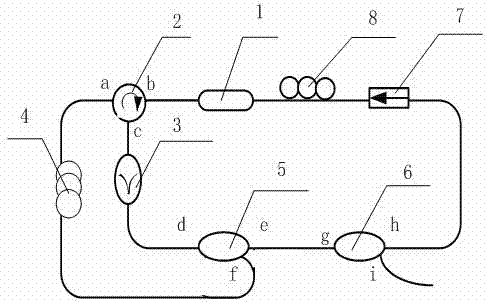
[0014] A dark pulsed fiber laser such as figure 1 As shown, it consists of a semiconductor optical amplifier 1, an optical circulator 2, a bandpass filter 3, a single-mode fiber 4, a 50:50 coupler 5, a 20:80 coupler 6, an optical isolator 7, and a polarization controller 8. The optical circulator 2, the 50:50 coupler 5, and the 20:80 coupler 6 have three ports respectively. One end of the semiconductor optical amplifier 1 is connected to the b port of the optical circulator 2, and the c port is connected to the optical circulator 2. The input terminal of the bandpass filter 3, the output terminal of the bandpass filter 3 is connected to the d port of the 50:50 coupler 5, the e port of the 50:50 coupler 5 is connected to the g port of the 20:80 coupler 6, and the 20:80 The h port of the coupler 6 is connected to the input end of the optical isolator 7, and the i port of the 20:80 coupler 6 is the output end of the laser, and the output laser is used for spectrometer, spectrum a...


PUM


Abstract

A dark pulse fiber laser consists of a semiconductor optical amplifier, an optical circulator, a band-pass filter, a single-mode fiber, a 50:50 coupler, a 20:80 coupler, an optical isolator and a polarization controller which are connected to one another through optical fibers so as to form two closed loops. By the dark pulse fiber laser, laser light in a resonant cavity is subjected to cross gain modulation and cross phase modulation through fed back laser light, and dark pulses can be generated. The dark pulse fiber laser has the advantages that the dark pulse fiber laser is simple in structure and low in cost, a pulse width tuning range is large, the dark pulse fiber laser can work at normal temperature, and the application prospect on the aspect of signal processing is high.

Description

technical field [0001] The invention belongs to the technical fields of optical fiber communication and optoelectronics, in particular to a dark pulse fiber laser. Background technique [0002] The laser output of a pulsed laser in the traditional sense is a bright pulse, that is, a sudden and significant increase in light intensity in a stable continuous light wave background. The theoretical design scheme of bright pulse lasers is very mature, and related technologies have been widely used in communication, laser ranging and other fields. However, when the bright pulse is transmitted in the optical waveguide, it is extremely sensitive to the noise and loss generated during the transmission process, causing its intensity to gradually decrease during the transmission process; and in the normal dispersion medium, the bright pulse cannot be transmitted like a soliton, Nonlinear effects cause spectral and temporal broadening of the pulse. These properties restrict the further...

Claims


Application Information

Patent Timeline
IPC IPC(8): H01S3/067H01S3/102
Inventor 潘洪刚薛玉明张爱玲王洛欣宋殿友
Owner TIANJIN UNIVERSITY OF TECHNOLOGY
Learn More