Supercharge Your Innovation With Domain-Expert AI Agents!

A constant load tensile test device

A tensile test, constant load technology, applied in the direction of applying stable tension/pressure to test the strength of materials, can solve the problems of easy falling off, non-removable frame structure, high price, etc., to achieve accurate and constant loading, manual loading Simple and easy to carry effect

Active Publication Date: 2017-10-13
725TH RES INST OF CHINA SHIPBUILDING INDAL CORP
View PDF2 Cites 1 Cited by
  • Summary
  • Abstract
  • Description
  • Claims
  • Application Information

AI Technical Summary

Problems solved by technology

[0002] Corrosion of metal materials in the marine environment is quite serious, which makes marine engineering and equipment materials have a great risk of stress corrosion cracking under stress, and may even cause metal materials to suddenly Fractures, major safety accidents, and economic losses caused by corrosion in the world are as high as trillions of dollars every year; therefore, it is very important to accurately evaluate the safety of marine engineering and equipment materials under the synergistic effect of corrosion factors and stress states in the marine environment. Important; the current constant load stress corrosion test is realized by large-scale special equipment, such as stress corrosion testing machine, universal testing machine, stress ring and spring device. Although this type of device can accurately measure the load, it is bulky, expensive and expensive. The stress corrosion test of a single specimen can only be carried out by professionals under laboratory conditions, and it is impossible to realize the batch test of multiple sets of specimens and the long-term exposure test in the actual marine environment
Chinese patent 201210222014.9 (application date July 2, 2012) discloses a high-temperature, high-pressure, constant-load stress corrosion test method and device. Constant load stress corrosion test under constant load. During the experiment, the metal material is subjected to the comprehensive action of constant stress, high temperature and high pressure gas phase, and liquid phase corrosion medium. The device has realized the miniaturization of the stress corrosion test device, but its preloading process requires the use of a tensile testing machine, which is inconvenient to operate, and no insulation measures are taken for the connection between the test piece and the clamping end , so that the test piece and the clamping end must use the same material, which limits the scope of use of the device; Chinese patent 201320180412.9 (application date April 11, 2013) discloses a portable axial tensile stress loading device, including a rectangular The load-bearing frame, the interior of the rectangular load-bearing frame is provided with more than one hollow structure arranged in parallel, and the hollow structure is equipped with slot holes symmetrically located on the upper and lower bottom central axes, the upper chuck is sleeved in the upper slot hole, and the lower slot hole A lower chuck is set in the middle sleeve, and one threaded end of the upper chuck passes through the slot hole above the frame to fit the loading nut, and the threaded end of the lower chuck passes through the slot hole below the frame to fit the lock nut; this device solves the problem of Accurate loading and simultaneous testing of multiple test pieces, but its frame structure is not disassembled, the loading method is complicated and cumbersome, it is impossible to realize the batch test of metal materials, and the test pieces are easy to fall off and lose after breaking; The constant load tensile test device for batch testing of metal materials under the actual marine environment and laboratory simulation conditions has great application prospects and social value

Method used


Image

  • A constant load tensile test device
  • A constant load tensile test device
  • A constant load tensile test device

Examples


Embodiment 1

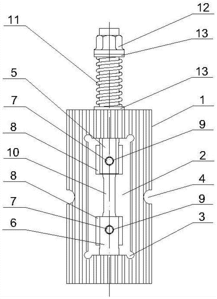
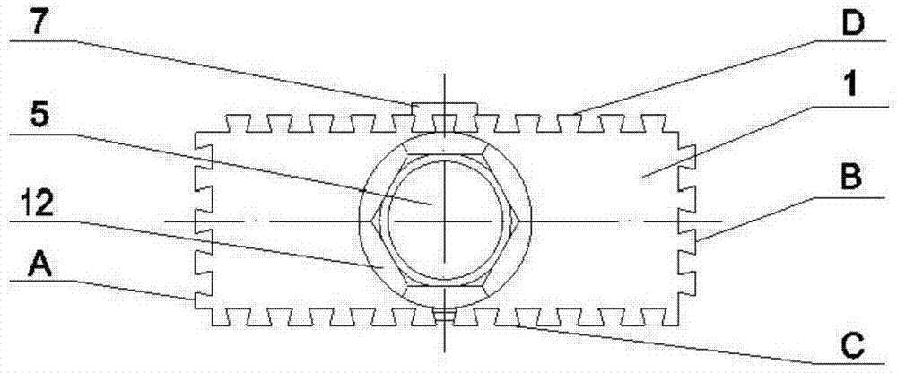
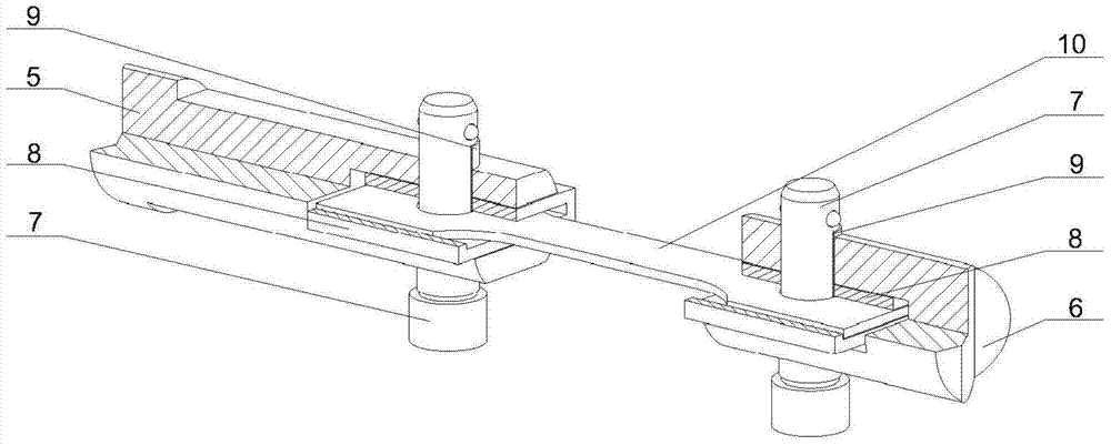
[0018] The main structure of the constant load tensile test device involved in this embodiment includes a load-bearing frame 1, a rectangular cavity 2, an arc-shaped groove 3, a fixing groove 4, an upper chuck 5, a lower chuck 6, and a pin 7 , an insulating gasket 8, an insulating bushing 9, a test piece 10, a loading spring 11, a loading nut 12 and an insulating washer 13; a hollow structure is formed in the bearing frame 1 including four sides of A, B, C and D Rectangular cavity 2, the four vertices of rectangular cavity 2 are formed with arc-shaped grooves 3 that can disperse the four right-angle loads of rectangular cavity 2, and the vertical central axis of the upper beam inside of load-bearing frame 1 is formed with a set The upper chuck 5 of the structure, the threaded end of the upper chuck 5 passes through the load-bearing frame 1 and is fitted with an insulating washer 13, a loading spring 11 and a loading nut 12. The lower chuck 6 of the set structure, the threaded ...

Embodiment 2

[0025] The single constant load tensile test device involved in this embodiment adds a fixed bolt 14 and a fixed flange nut 15 on the basis of embodiment 1. In the actual marine environment exposure test, according to the test requirements and the loading method of embodiment 1, A set constant load is applied to a set number of test pieces 10, and the constant load tensile test device equipped with the test pieces 10 of the same test period is plugged in the way that A faces the B side, and the test pieces 10 with different test periods are installed. The constant load tensile test device of the specimen 10 is plugged in such a way that the C faces the D face, and multiple constant load tensile test devices form an array combination, and the fixed grooves 4 on the adjacent A and B faces of each load-bearing frame 1 The fixing bolts 14 are penetrated into the round holes formed by the splicing, and the fixing bolts 14 are fastened with the fixing flange nuts 15, and the combined...

Embodiment 3

[0027] The single constant load tensile test device involved in this embodiment has the same structure as that of Embodiment 1. In the simulated marine environment in the laboratory, according to the test requirements and the loading method of Embodiment 1, a set number of test pieces 10 are loaded and set. The constant load, the constant load tensile test device is plugged in the way that A faces the D face and B faces the C face, and is rotated in a counterclockwise or clockwise order, and the adjacent constant load tensile test devices are 90 to each other. °Right angles form a wrap-around combination; when there are a large number of constant load tensile test devices, insert them in the way of A facing B and then perform wrap-around combination plugging; place the plugged constant load tensile test devices in a simulated ocean In the environment, the batch test of the simulated marine environment in the laboratory of 10 test pieces is realized.

[0028] When the present e...


PUM


Abstract

The invention belongs to the technical field of metal material test equipment, and relates to a constant load tensile test device, which comprises a rectangular cavity in the load-bearing frame of the four sides of A, B, C and D, and four vertices of the rectangular cavity are formed with The arc-shaped groove that can disperse the four right-angle loads of the rectangular cavity, the vertical central axis on the inner side of the upper beam of the load-bearing frame is made with a sleeve-type upper chuck, and the threaded end of the upper chuck passes through the load-bearing frame sleeve type Insulating washers, loading springs and loading nuts are made, and a lower chuck with a set structure is formed on the vertical central axis inside the lower beam of the load-bearing frame. The threaded end of the lower chuck is fixedly connected to the load-bearing frame, the upper chuck and the lower chuck The clamping ends are respectively made with U-shaped groove structure, and the center of both sides of the U-shaped groove structure is made with insulating gaskets; it is small and light, easy to carry, assemble and fix, and can be freely inserted to realize batch testing of the test pieces, safe and reliable , The manual loading method is simple, and the loaded load is accurate and constant.

Description

Technical field: [0001] The invention belongs to the technical field of metal material test equipment, and relates to a constant load tensile test device, which is suitable for batch testing and testing of metal materials in actual marine environments and laboratory simulated marine environments. Background technique: [0002] Corrosion of metal materials in the marine environment is quite serious, which makes marine engineering and equipment materials have a great risk of stress corrosion cracking under stress, and may even cause metal materials to suddenly Fractures, major safety accidents, and economic losses caused by corrosion in the world are as high as trillions of dollars every year; therefore, it is very important to accurately evaluate the safety of marine engineering and equipment materials under the synergistic effect of corrosion factors and stress states in the marine environment. Important; the current constant load stress corrosion test is realized by large-s...

Claims


Application Information

Patent Timeline
Patent Type & Authority Patents(China)
IPC IPC(8): G01N3/08
Inventor 范林郭为民侯健
Owner 725TH RES INST OF CHINA SHIPBUILDING INDAL CORP
Features
  • R&D
  • Intellectual Property
  • Life Sciences
  • Materials
  • Tech Scout
  • Unparalleled Data Quality
  • Higher Quality Content
  • 60% Fewer Hallucinations
Learn More