Rotary die-cutting die roller directly formed by laser cladding

A technology of rotating molds and mold rollers, which is applied in metal material coating process, metal processing, coating, etc. It can solve the problems such as the great difference between the wall thickness of the model and the thickness of the substrate, difficulty in maintaining accuracy, and coarse grains in the internal structure. , to achieve the moment of inertia of the good mold roller, reduce the need for subsequent processing, and control the cost

Active Publication Date: 2015-07-08
FUJIAN UNIV OF TECH
View PDF7 Cites 3 Cited by
  • Summary
  • Abstract
  • Description
  • Claims
  • Application Information

AI Technical Summary

Problems solved by technology

There are two major problems in the milling forming process for the manufacture of tools with relatively large diameters: 1. During the overall heat treatment, due to the complex structure of the roller body model, the wall thickness of the model is very different from the thickness of the substrate, and the material of powder metallurgy high-speed steel or cemented carbide is large. Diameter rolls are prone to severe deformation, coarse grains in the internal structure, cracks and other problems during heat treatment and quenching; 2. The overall milling process has large cutting volume, low processing efficiency, and serious waste of materials
The main problems in the insert molding process are: 1. It is difficult to realize the gapless insert assembly technology, and it is difficult to maintain the accuracy under long-term high-speed working conditions; 2. The size adaptation range is narrow, because only large-size mold rolls have It is possible to divide the edge curve into several inserts and use insert molding

Method used


Image

  • Rotary die-cutting die roller directly formed by laser cladding
  • Rotary die-cutting die roller directly formed by laser cladding
  • Rotary die-cutting die roller directly formed by laser cladding

Examples


Embodiment Construction

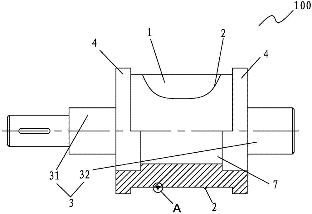
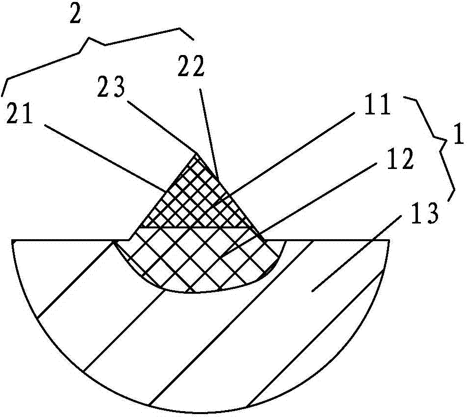
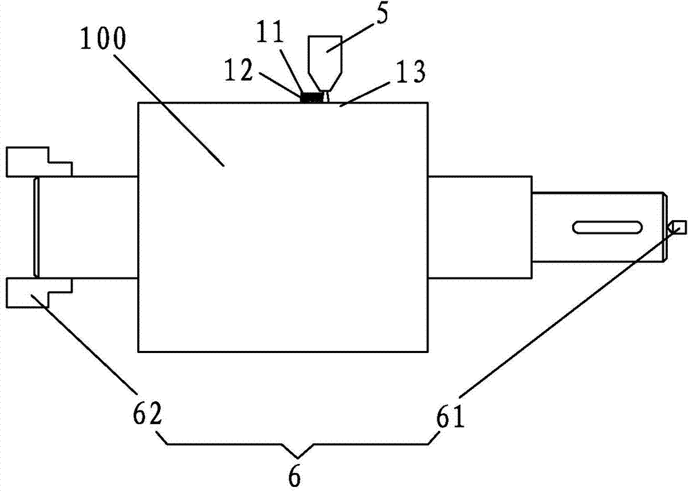
[0027] see figure 1 and figure 2 As shown, a mold roll of a rotary die-cutting equipment includes a roll body 1 on which a blade 2 is provided, and the roll body 1 adopts a laser cladding process to form a cladding layer 11 from the outside to the inside. 1. The layered structure of the transition layer 12 and the matrix 13, the cladding layer 11 constitutes the blade 2, and the transition layer connects the blade 2 and the matrix 13; the roller body is a hollow structure.

[0028] The laser cladding process realizes the metallurgical bonding between the substrate and the cladding layer through the deposition of metal alloys or other types of materials on the substrate, and obtains a non-porous, fine-grained microstructure, and cladding with good mechanical properties Floor. Compared with laser sintering and coating processes such as plasma spraying and high-speed flame spraying, the bonding and friction properties of the cladding layer are better; compared with other metal...


PUM


Abstract

The invention relates a rotary die-cutting die roller directly formed by laser cladding, and provides a die roller of a rotary die-cutting device. The die roller comprises a roller body on which a blade is arranged; a cladding layer, a transition layer and a layered structure of a base body are formed on the roller body from inside to outside in a sequence by the laser cladding process, wherein the cladding layer is used for forming the blade; the transition layer is connected with the blade and the base body; the roller body is of a hollow structure. According to the die roller formed by the laser cladding process, different materials can be subjected to metallurgical combination; the dilution rate is small; the hardness and wear resistance of the blade body material are maintained; the flexibility of the base body material is remained; the blade body material and the base body material can be combined well; the section of a blade body is of a near net shape, so that the later precision processing workload can be reduced; the cladding track can be digitally controlled; any complex blade curved line can be pre-designed; the roller body is of the hollow structure so that the heat dispersing performance of the base body is improved, and the mechanical property of the blade can be improved; in addition, the weight of the die roller is reduced, and thus the rotary inertia of the die roller can be increased.

Description

【Technical field】 [0001] The invention relates to the technical field of die-cutting processing, in particular to a molding method of a die roller of a rotary die-cutting device and a blade thereof. 【Background technique】 [0002] As a traditional and classic manufacturing technology, die-cutting technology has been widely used in more than a dozen industries such as printing, packaging, mobile phone digital accessories, health and medical supplies, and electronic labels. Due to a series of problems such as poor safety, low automation procedures, and high energy consumption, traditional flat die-cutting equipment is being eliminated by the market, so the market for rotary die-cutting equipment is expanding rapidly. [0003] The core component of the rotary die-cutting equipment is the die-cutting tool holder, which is composed of a die roller, a round roller and a die frame. Wherein the die roller body is manufactured with a knife edge according to the shape of the processe...

Claims


Application Information

Patent Timeline
IPC IPC(8): B26F1/42C23C24/10
CPCB26F1/42C23C24/103
Inventor 江吉彬曾寿金陈阳升陈丙三叶建华
Owner FUJIAN UNIV OF TECH
Why Eureka
Try Eureka