Automatic machining equipment and machining method for pantograph carbon slide plate of high-speed rail

A pantograph carbon sliding plate and processing equipment technology, which is applied to stone processing equipment, metal processing equipment, stone processing tools, etc. The trouble of direct programming, the expansion of the scope of adaptation, the effect of high production efficiency

Active Publication Date: 2015-07-15
ZHE JIANG CHENLONG SAWING MACHINE CO LTD
View PDF6 Cites 13 Cited by
  • Summary
  • Abstract
  • Description
  • Claims
  • Application Information

AI Technical Summary

Problems solved by technology

In the casting process, it is easy to produce bad impurities and waste products. At the same time, due to the poor finish of the cast surface, all four sides need to be processed, which not only wastes a lot, but also has low production efficiency.
In addition, the carbon slider is a brittle material, and it is difficult to clamp the narrow and long workpiece, especially the processing of the middle curved groove, which needs to be consistent with the internal radian, but the secondary clamping during processing will have a negative impact on the dimensional accuracy

Method used


Image

  • Automatic machining equipment and machining method for pantograph carbon slide plate of high-speed rail
  • Automatic machining equipment and machining method for pantograph carbon slide plate of high-speed rail
  • Automatic machining equipment and machining method for pantograph carbon slide plate of high-speed rail

Examples


Embodiment Construction

[0032] In order to make the technical problems, technical solutions and beneficial effects to be solved by the present invention clearer, the present invention will be further described in detail below in conjunction with the accompanying drawings and embodiments. It should be understood that the specific embodiments described here are only used to explain the present invention, not to limit the present invention.

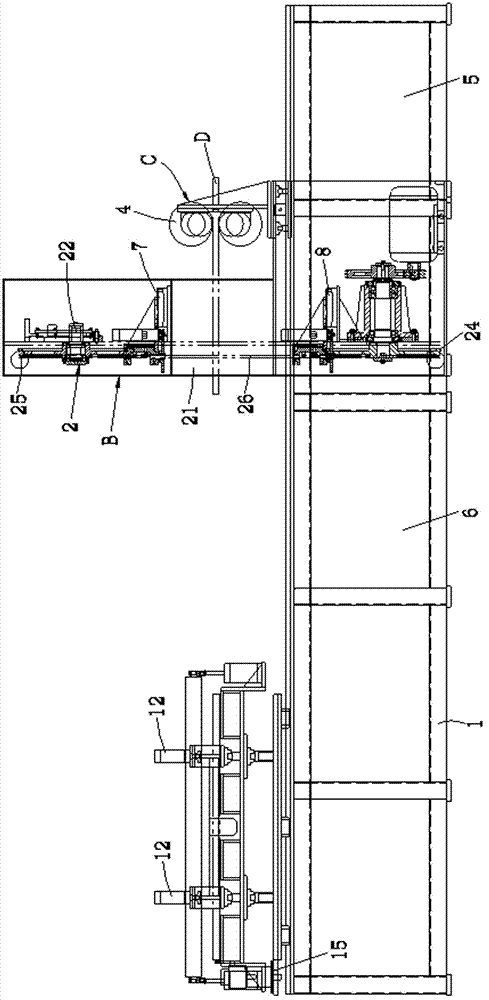
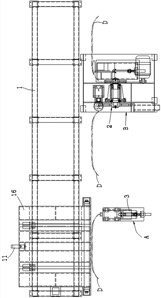
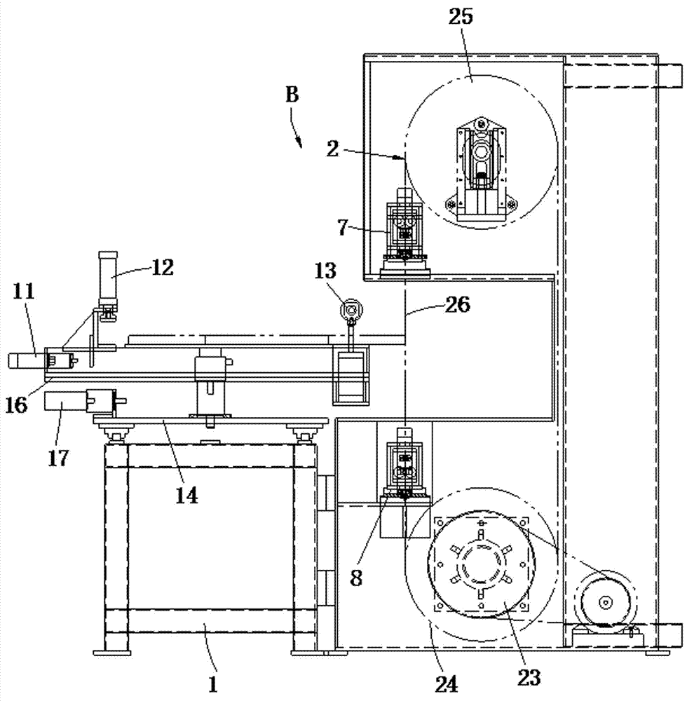
[0033] Please also refer to figure 1 , figure 2 as well as image 3 As shown, the preferred embodiment of the automatic processing equipment for high-speed iron pantograph carbon slide plate and the processing method thereof of the present invention is provided with milling station A, sawing station B and chamfering station C in sequence, including frame 1, belt Sawing machine 2, workpiece milling device 3, workpiece chamfering device 4, CNC numerical control system 5 and pneumatic system 6.

[0034] The band sawing machine 2, the workpiece milling device 3 and...


PUM


Abstract

The invention relates to automatic machining equipment and a machining method for a pantograph carbon slide plate of a high-speed rail. The automatic machining equipment is sequentially provided with a milling station, a sawing station and a chamfering station and comprises a machine stand, a band sawing machine, a workpiece milling device, a workpiece chamfering device, a CNC (Computer Numerical Control) system and a pneumatic system; a carbon slide plate workpiece to be machined is arranged on the machine stand and is sequentially subjected to milling, sawing and chamfering machining; a saw frame of the band sawing machine is also provided with a saw band upper guide servo rotating device and a saw band lower guide servo rotating device which are capable of freely, synchronously and correspondingly rotating a band saw blade within a certain range. According to the automatic machining equipment and the machining method disclosed by the invention, the carbon slide plate can be machined in a sawing manner, and the working procedures, namely sawing, milling and chamfering are integrated on one equipment and can be automatically finished after once clamping, so that materials are saved and the working efficiency is improved.

Description

technical field [0001] The invention belongs to the technical field of band sawing machine equipment, and in particular relates to an automatic processing equipment and a processing method for a high-speed rail pantograph carbon slide plate. Background technique [0002] The pantograph, also known as the pantograph, is an electrical device for high-speed trains to receive electric energy from the catenary, and is installed on the roof. It is so named because the shape of the rhombic pantograph looks like an open bow when viewed from the side. Generally, it can be divided into single-arm bow and double-arm bow. At present, the single-arm pantograph is commonly used. The carbon slide is one of the key components of the pantograph. When the train is running, the carbon slide plate and the train line slide plate are mainly in direct contact with the contact wire. There are mainly four types of carbon skateboards currently on the market: pure metal skateboards, powder metall...

Claims


Application Information

Patent Timeline
Patent Type & Authority Applications(China)
IPC IPC(8): B28D1/08B28D1/18B28D1/00
CPCB28D1/003B28D1/086B28D1/18B28D7/005B23D55/082B23D55/10B28D1/08B60L5/24B60L2200/26B60Y2200/30B23C3/12B23C3/28B23D55/08
Inventor 丁侠胜丁泽林江平
Owner ZHE JIANG CHENLONG SAWING MACHINE CO LTD
Why Eureka
Try Eureka