Biomass burner

A burner and biomass technology, applied in combustion methods, combustion equipment, solid fuel combustion, etc., can solve the problems of easy blockage of biomass particles, low motor power, and reduction of biomass particles, so as to solve the problem of equipment not operating normally , High combustion efficiency and full combustion effect

Active Publication Date: 2015-07-22
ZHE JIANG ECO ENVIRONMENTAL TECH CO LTD
View PDF5 Cites 1 Cited by
  • Summary
  • Abstract
  • Description
  • Claims
  • Application Information

AI Technical Summary

Problems solved by technology

[0008] The purpose of the present invention is to provide a biomass burner. By simply changing the transmission structure, it can solve the problem that the biomass particles are

Method used


Image

  • Biomass burner
  • Biomass burner
  • Biomass burner

Examples


Embodiment 1

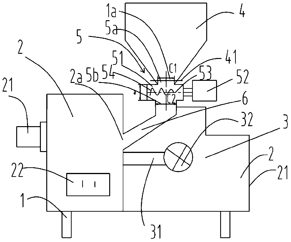
[0036] figure 2 It is a schematic structural diagram of Embodiment 1 of a biomass burner of the present invention; image 3 It is a top view structure schematic diagram of the feeding part of a biomass burner of the present invention;

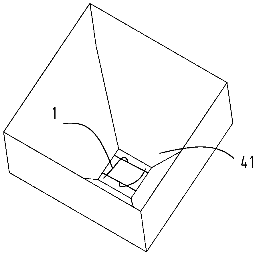
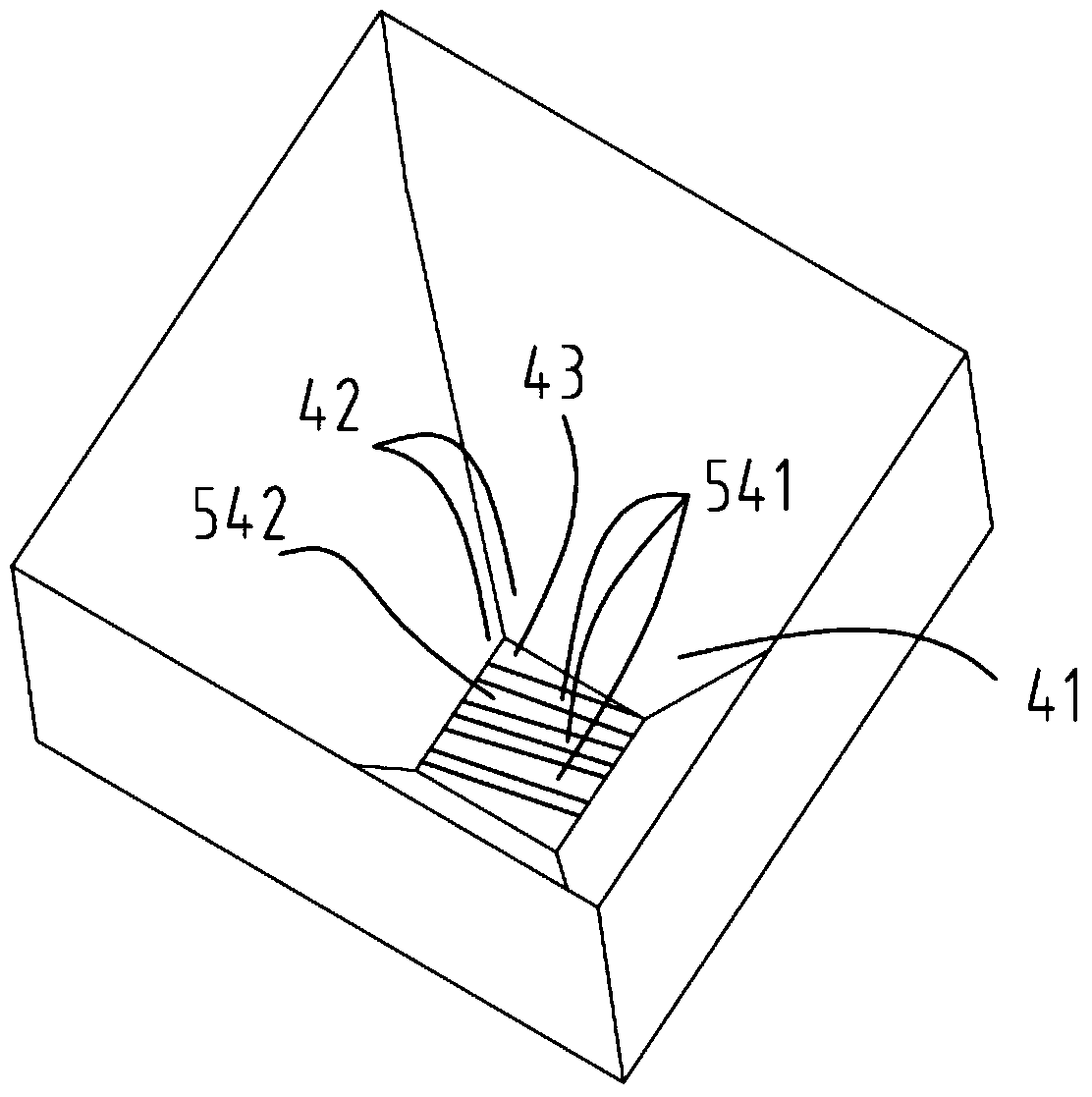
[0037] Such as figure 2 and image 3 As shown, a biomass burner includes a frame 1, a combustion chamber 2 arranged on the frame, an air chamber 3 located on one side of the combustion chamber, and a storage bin 4 located above the air chamber 3. The air chamber 3 and The combustion chamber 2 communicates with the air-introduction channel 31, and one end of the air-induction channel 31 is provided with a blower fan 32, and the other end leads into the combustion chamber 2; the combustion chamber 2 communicates with the storage bin 4, and the biomass particles The bin 4 enters the combustion chamber 2 for combustion, and the combustion chamber 2 is also provided with a flame nozzle 21 and an ash outlet 22, and also includes a feeding module...

Embodiment 2

[0045] Figure 7 It is a structural schematic diagram of Embodiment 2 of a biomass burner of the present invention. Such as Figure 7 As shown, the series feeding module 7 shown in this embodiment includes two sets of feeding modules 5 connected in series, and the biomass particle fuel enters the feeding module 5 through the feed bin and then enters the combustion chamber 2 . In this example, the two feeding modules 5 of the feeding module 10 are respectively driven by two shut-off fans 72, and the shut-off fans 72 are the same as the shut-off fans 52 in the embodiment. Of course, the two sets of feeding modules 5 can also be driven by one quantitative feeder. In this embodiment, except for the differences described above, other structures, positional relationships and connection relationships are the same as those in Embodiment 1.


PUM


Abstract

The invention relates to a biomass burner. The biomass burner comprises a rack (1), a combustion chamber (2), a wind chamber (3) and a storage bin (4). The wind chamber (3) is communicated with the combustion chamber (2) through an air induced channel (31). One end of the air induced channel (31) is provided with a draught fan (32). The other end of the air induced channel (31) extends inside the combustion chamber (2). Biomass particles enter the combustion chamber (2) from the storage bin (4) to be subjected to combusting. A boccacrater (21) and a dust outlet (22) are further arranged on the combustion chamber (2). The biomass burner further comprises a feeding module (5). The feeding module (5) comprises a feeding channel (51) and a spiral shaft (53). A bevel gear (54) is arranged on the spiral shaft (53). An inclined shearing opening (43) is formed by helical teeth (541) of the bevel gear (54) and the wall face (42) of a material outlet (41). The biomass particles enter a channel inlet (5a) from the inclined shearing opening (43). The problem that the device cannot work normally due to the fact that the biomass particles easily block the material outlet is solved, quantitative feeding is achieved, the heat power is continuous and adjustable, automatic controlling is achieved, the shearing effect is good, and the phenomena of material blocking and tempering are avoided.

Description

technical field [0001] The invention belongs to the key technical field of green energy equipment manufacturing, and in particular relates to a biomass burner. Background technique [0002] In today's rapid social and economic development, the dual nature of resource conservation and environmental friendliness has become a decisive factor for the sustainable development of various countries. With the development of society and economy, the demand for primary energy is increasing day by day, and the consumption of fossil fuels such as coal and oil has aggravated the pollution of the environment. Therefore, looking for a renewable alternative energy source to reduce greenhouse gas emissions has become the focus of attention of countries all over the world. Biomass energy is a renewable and clean energy with high volatility and low pollution. my country has abundant biomass resources. As far as my country's basic national conditions and biomass resources are concerned, it is u...

Claims


Application Information

Patent Timeline
IPC IPC(8): F23B40/00F23K3/16
Inventor 车磊
Owner ZHE JIANG ECO ENVIRONMENTAL TECH CO LTD
Why Eureka
Try Eureka