X-ray target assembly

A target assembly, X-ray technology, used in X-ray tube parts, X-ray/γ-ray/particle irradiation therapy and other directions, can solve the problems of easy corrosion, poor heat dissipation, unusable, etc., to prevent oxidation and The effect of surface corrosion, increasing X-ray dose rate and increasing incident power

Active Publication Date: 2015-07-22
SHANGHAI UNITED IMAGING HEALTHCARE
View PDF6 Cites 3 Cited by
  • Summary
  • Abstract
  • Description
  • Claims
  • Application Information

AI Technical Summary

Problems solved by technology

[0006] The disadvantages of this target assembly are: firstly, due to the contact between the target material and the air, and the high temperature of the bombarded part of the target material, this part is easily oxidized and corroded; secondly, the heat dissipation of the target material is not good. The service life can only reduce the incident power of the high-energy electron beam to ensure that the target compo...

Method used


Image

  • X-ray target assembly
  • X-ray target assembly
  • X-ray target assembly

Examples


Embodiment 1

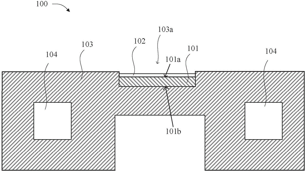
[0031] This embodiment provides an X-ray target assembly 100, refer to image 3 , including a target 101 , a heat conduction layer 102 and a heat dissipation part 103 .

[0032] combine Figure 4-5 As shown, the target 101 has a first surface 101a receiving high-energy electron beam bombardment, and a second surface 101b opposite to the first surface 101a, the first surface 101a has a bombarded part A, and the heat conduction layer 102 covers the first surface 101a And stick to the first surface 101a.

[0033] The heat conduction layer 102 is a key component in the structure of this embodiment. Theoretically, the selection conditions for the material of the heat conduction layer 102 are: the larger the thermal conductivity, the better, the lower the density, the better, and the smaller the thickness. In this embodiment, the material of the thermal conduction layer 102 is graphite or a modified graphite material.

[0034] The cooling part 103 is made of heat-conducting metal...

Embodiment 2

[0049] The difference between this embodiment and Embodiment 1 is that, referring to Figure 4-5 and combine Figure 8 As shown, the thermal conduction layer 102 structurally includes a base layer 102a and an anti-oxidation layer 102b, and the base layer 102a is at least one of beryllium, iron, or modified materials of beryllium and iron.

[0050] Wherein, the base layer 102a is at least bonded to the bombarded part A, and the anti-oxidation layer 102b is located on the side of the base layer 102a opposite to the bombarded part A, covers the base layer 102a and is bonded to the base layer 102a.

[0051] If the modified material of beryllium and iron used as the base layer 102a has oxidation resistance, the anti-oxidation layer 102b can be omitted.

[0052] In order to reduce the influence of the heat conduction layer 102 on the beam spot and energy spectrum of the incident electron beam, the heat conduction layer 102 needs to meet at least: the thermal conductivity of the hea...


PUM

PropertyMeasurementUnit
Thermal conductivityaaaaaaaaaa
Densityaaaaaaaaaa
Thermal conductivityaaaaaaaaaa

Abstract

An X-ray target assembly comprises target material and a heat conduction layer, wherein the target material has a first surface for receiving high-energy electron beam bombardment, and the first surface is provided with a bombardment-suffering part, and the heat conduction layer at least covers the bombardment-suffering part and is attached to the bombardment-suffering part. The heat conduction layer enables the bombardment-suffering part of the target material to be isolated from the air and enables heat energy of the bombardment-suffering part to be radiated quickly. Therefore, the incident power of a high-energy electron beam can be enhanced and the X-ray dose rate can be improved while the bombardment-suffering part of the target material can be prevented from oxidation and surface corrosion.

Description

technical field [0001] The invention relates to the field of medical equipment, in particular to an X-ray target assembly. Background technique [0002] X-rays are widely used in modern medical diagnosis and treatment, especially tumor treatment. [0003] In the prior art, a high-energy electron beam bombards a target, and bremsstrahlung (a type of radiation produced when high-energy charged particles are suddenly decelerated) occurs in the target to generate X-rays. The high-energy electron beam is generally formed by high-voltage acceleration of an accelerator, and the target material can be made of materials such as tungsten, gold, thallium, iron, copper, and nickel. [0004] When the high-energy electron beam bombards the target, the conversion efficiency of X-rays is very low, usually only about 15%, and most of the energy of the high-energy electron beam is absorbed by the target to generate heat. When the dose rate required by the machine is greater (the X-ray dose ...

Claims


Application Information

Patent Timeline
IPC IPC(8): H01J35/02A61N5/10
Inventor 刘艳芳李贵徐峰
Owner SHANGHAI UNITED IMAGING HEALTHCARE
Why Eureka
Try Eureka