Control of gas composition of a gas separation system having membranes

A gas separation and membrane separation technology, applied in the field of biogas or natural gas treatment, can solve the problems of expensive, inconvenient, and unfavorable energy control technology, and achieve the effect of a simple, accurate and simple control system

Active Publication Date: 2015-07-22
EVONIK OPERATIONS GMBH
View PDF10 Cites 9 Cited by
  • Summary
  • Abstract
  • Description
  • Claims
  • Application Information

AI Technical Summary

Problems solved by technology

This is disadvantageous in terms of energy and expensive and inconvenient in terms of control technology, so it is less commercially attractive
Furthermore, as explained above, it is not possible to adjust the main pressure in a tertiary interconnection arrangement to affect the permeate quality independently of the retentate texture

Method used


Image

  • Control of gas composition of a gas separation system having membranes
  • Control of gas composition of a gas separation system having membranes
  • Control of gas composition of a gas separation system having membranes

Examples


Embodiment 1

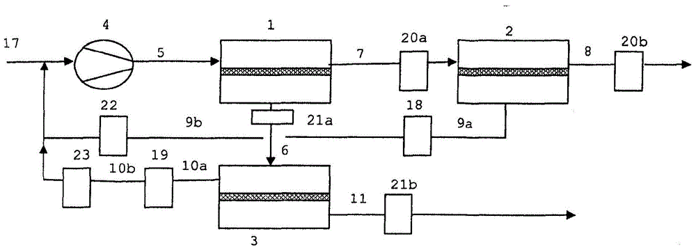
[0116] The purpose of this experiment was to find the calibration straight line that allows maintaining the product in retentate stream 8 by changing the permeate pressure of retentate separation stage 2 when the feed flow rate or compressor speed in feed stream 5 is changed The gas quality is constant, and the exhaust gas quality in the permeate stream 11 is kept constant by varying the retentate pressure of the permeate separation stage 3 .

[0117] To this end, in a 3-stage interconnection arrangement operated according to the general experimental arrangement, the compressor efficiency was increased stepwise. An attempt was then made to keep the exhaust gas concentration 11 and the product gas concentration 8 constant within narrow ranges by varying the permeate pressure of retentate separation stage 2 and the retentate pressure of permeate separation stage 3 . As the compressor efficiency increased from an initial 60% to a final 75%, the feed volume flow5 increased from 3....

Embodiment 2

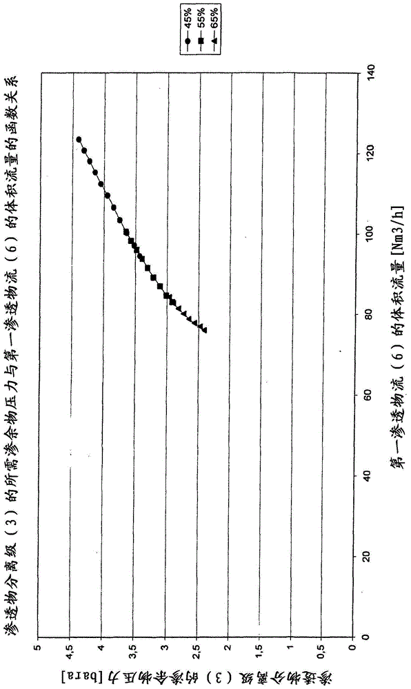
[0126] It was checked whether by changing the retentate pressure of the permeate separation stage 3 using the control unit 19 in the third retentate stream 10 a change in the methane concentration in the exhaust gas from this unit (third permeate stream 11 ) could be achieved and obtain a calibration curve. This calibration relationship can then be used to adapt the methane content in the exhaust if there is a change in the measurement of the exhaust concentration.

[0127] To this end, while keeping the compressor speed constant, the retentate pressure of the permeate separation stage 3 is varied with the control device 19 in the third retentate stream 10 and the correspondingly varied third permeate stream 11 (exhaust gas ) methane concentration. The volumetric flow rate of the device is also recorded. Values ​​are shown in Table 2.

[0128] Table 2:

[0129]

[0130] As shown in Table 2, as the retentate pressure in permeate separation stage 3 increases, the methane ...

Embodiment 3

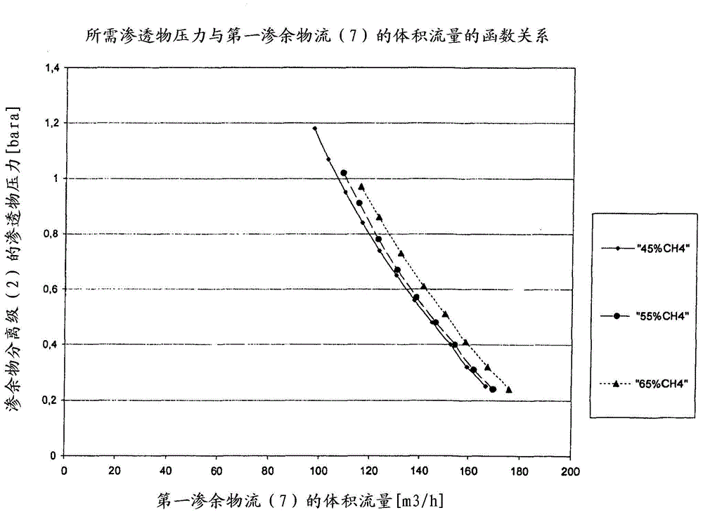
[0133] Variation of the methane concentration in the product gas (=second retentate stream 8 ) of this unit can be achieved by varying the permeate pressure of the retentate separation stage 2 with the control unit 18 in the second permeate stream 9a. This calibration relationship can be used to adapt the methane content in the product gas if there is a change in the measurement of the product gas concentration.

[0134] For this purpose, the permeate pressure of retentate separation stage 2 was varied while the compressor speed was kept constant and the methane concentration in the product gas was measured as a result of the variation. Values ​​are shown in Table 3.

[0135] table 3:

[0136] Stage 2 Permeate Pressure [bara]

c(CH in retentate stream 8 4 )[%]

1.005

96.44

0.95

96.77

0.9

97.03

0.85

97.23

0.8

97.48

0.75

97.68

0.7

97.93

0.65

98.14

0.6

98.34

0.5...


PUM


Abstract

The invention relates to a method for controlling a gas separation system comprising membrane separation stages, a system controlled by said method and use of said system for separation of gas mixtures, in particular in the preparing of biogas or natural gas or synthesis gas.

Description

technical field [0001] The invention relates to a method for controlling a gas separation device, a device controlled thereby and its use for separating gas mixtures, in particular in the treatment of biogas or natural gas. Background technique [0002] Membranes are known for use with which gases can be separated from one another relatively easily in a pressure-driven process. The gases are separated from one another here with little effort, but mostly also with a lower purity of the product. Especially when, in the case of gas mixtures, both components of the binary mixture are to be separated in as pure a form as possible, in contrast to the case of simple single-stage interconnection arrangements (where, for example, only the retentate component has to be prepared in a certain purity , and the permeate can be disposed of (for example, nitrogen from air) compared to the technical layout of the membrane and the control of the process need to invest more money. For exampl...

Claims


Application Information

Patent Timeline
Patent Type & Authority Applications(China)
IPC IPC(8): B01D53/22C10L3/10C01B32/40
CPCB01D2317/027C10L2290/548Y02C10/10B01D2257/504B01D71/64Y02E50/343B01D53/22B01D2258/05B01D53/226C12M47/18C10L3/104C10L2290/46B01D2256/245C10L2290/58Y02P20/59Y02P20/145Y02C20/40Y02E50/30B01D53/228B01D63/00B01D2053/221B01D2311/14
Inventor M·安格兰克H·勒格尔
Owner EVONIK OPERATIONS GMBH
Why Eureka
Try Eureka