Optical field matching filtering range finding device based on M-sequence phase coding

A technology of optical matching and phase encoding, which is applied in measurement devices, radio wave measurement systems, electromagnetic wave re-radiation, etc., can solve the problems of high operating environment requirements and high price, and achieve high sensitivity, easy phase and frequency shift , The effect of reducing the requirements for detection bandwidth

Active Publication Date: 2015-08-05
SHANGHAI INST OF OPTICS & FINE MECHANICS CHINESE ACAD OF SCI
View PDF4 Cites 9 Cited by
  • Summary
  • Abstract
  • Description
  • Claims
  • Application Information

AI Technical Summary

Problems solved by technology

However, since the range resolution of the phase-encoded waveform is proportional to the phase modulation rate, that is, the higher the modulation rate, the higher the range resolution, but the higher the modulation rate, the higher the bandwidth requirements of the detector under the condition of heterodyne detection The higher it is, the respo

Method used


Image

  • Optical field matching filtering range finding device based on M-sequence phase coding
  • Optical field matching filtering range finding device based on M-sequence phase coding
  • Optical field matching filtering range finding device based on M-sequence phase coding

Examples


Embodiment Construction

[0024] The present invention will be described in further detail below in conjunction with the accompanying drawings and embodiments, but the protection scope of the present invention should not be limited thereby.

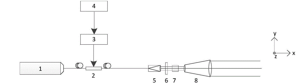
[0025] figure 1 It is a schematic diagram of the principle of the high-speed phase modulation transmitter of the present invention and the corresponding coordinate system position in the diagram. As can be seen from the figure, the high-speed phase modulation transmitter of the present invention includes a laser light source 1, a broadband optical phase modulator 2, a microwave amplifier 3, an M-sequence signal waveform generator 4, an optical fiber collimator 5, a transmitter half-wave plate 6, and a transmitter polarizer Beam splitter 7 and laser beam expander 8;

[0026] Such as figure 1 , 2 , 3, 5 in the unified coordinate system, the definition figure 1 and figure 2 The main optical axis of transmitting and receiving is the x-axis, in figure 1 , 2 In ...


PUM


Abstract

An optical field matching filtering range finding device based on M-sequence phase coding comprises a high-speed phase modulating and transmitting end, and a low-speed receiving end. The optical field matching filtering range finding device has advantages of high-speed modulation, high-speed receiving, random distribution for detecting light and reference light strength, no requirement for electronic signal processing, no range finding result effect by target echo waveform interference from multiple distances. A rectangular prism which is driven by a stepping motor is used for adjusting time delay of local reference light, so that a phase coding signal is focused through matched filtering. A relative distance between target points is measured through light path delay of the stepping motor. The optical field matching filtering range finding device acquires distance information through a high-speed phase coding signal, and can obtain a relatively high laser coding signal repetition frequency and a relatively high distance resolution. A low-speed detector which is adopted effectively reduces the requirement of the system to electronic components. The optical delay which is introduced by the stepping motor eliminates an electronic signal processing step.

Description

technical field [0001] The invention relates to phase code distance measurement, more specifically, an optical domain matched filter distance measurement device based on M-sequence phase code. Background technique [0002] In the field of coherent range-Doppler lidar imaging and scanning 3D imaging lidar, various phase encoding waveforms are usually used to obtain the relative distance information of the detection target, and the waveform compression processing based on matched filtering is the key to obtaining relative distance information from the phase encoding waveform The only means of information processing. However, since the range resolution of the phase-encoded waveform is proportional to the phase modulation rate, that is, the higher the modulation rate, the higher the range resolution, but the higher the modulation rate, the higher the bandwidth requirements of the detector under the condition of heterodyne detection The higher it is, the response bandwidth of th...

Claims


Application Information

Patent Timeline
IPC IPC(8): G01S17/08
CPCG01S17/08
Inventor 孙建锋蔡光宇刘福川张国马小平李光远刘立人
Owner SHANGHAI INST OF OPTICS & FINE MECHANICS CHINESE ACAD OF SCI
Why Eureka
Try Eureka