Sinter cooler waste gas afterheat gradient utilization method and device thereof

A technology of sintering cooling machine and cooling machine, which is applied in the field of waste heat utilization and environmental protection in the iron and steel industry

Inactive Publication Date: 2015-08-12
HUNAN ZHONGYE CHANGTIAN ENERGY CONSERVATION & ENVIRONMENTAL PROTECTION TECH CO LTD
View PDF5 Cites 5 Cited by
  • Summary
  • Abstract
  • Description
  • Claims
  • Application Information

AI Technical Summary

Problems solved by technology

The whole system has no exhaust gas and will not pollute the environment. It not only utilizes the waste

Method used


Image

  • Sinter cooler waste gas afterheat gradient utilization method and device thereof
  • Sinter cooler waste gas afterheat gradient utilization method and device thereof
  • Sinter cooler waste gas afterheat gradient utilization method and device thereof

Examples


Embodiment 1

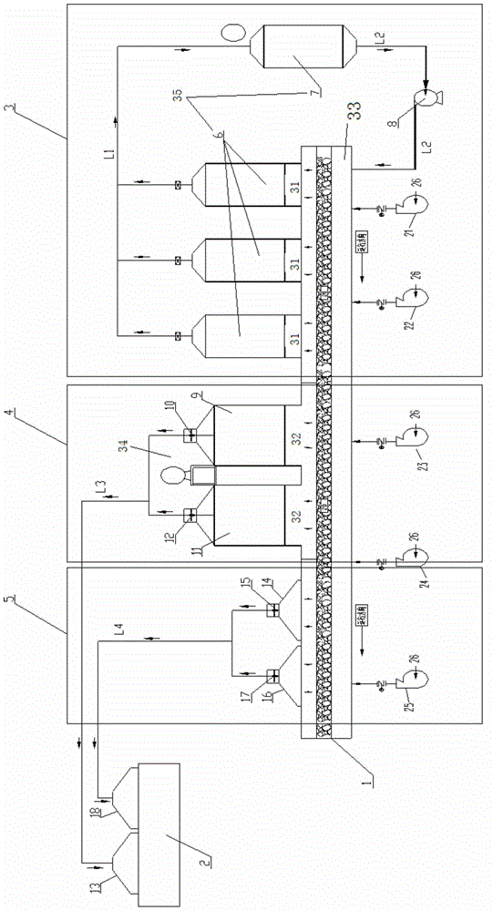
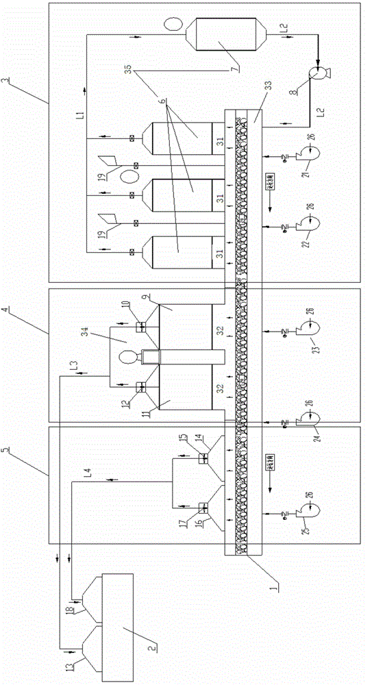
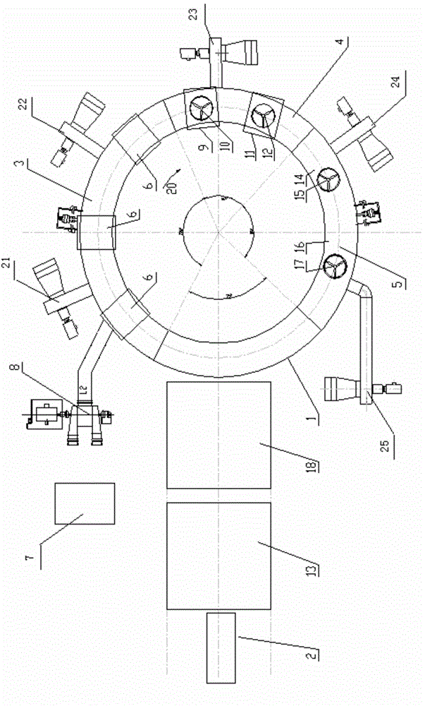
[0097] Such as figure 1 As shown, a zero-emission device for waste heat cascade utilization of sintering cooler exhaust gas is characterized in that: the cooling section of sintering cooler 1 is divided into high temperature zone 3, medium temperature zone 4 and low temperature zone 5, and the waste gas in high temperature zone 3 of sintering cooler passes through double The pressure waste heat boiler 35 produces two steams with one high pressure and one low pressure, that is, the first steam (pressure 1.8MPa, temperature 360°C) and the second steam (pressure 0.5MPa, temperature 180°C); The steam is generated by the single-pressure waste heat boiler 34; the waste gas from the low-temperature zone 5 of the sinter cooler 1 is transported to the top of the material layer of the sinter machine 2 (ie, inside the No. 2 wind hood 18) through the pipeline L4. The dual-pressure waste heat boiler 35 in the high-temperature zone 3 of the sinter cooler includes multiple (for example, thre...

Embodiment 2

[0112] Example 1 is repeated, except that the high-parameter heat exchange assembly 6 in the high-temperature zone is composed of five high-parameter heat exchange groups.

Embodiment 3

[0114] Repeat Example 1, except that the boiler section 9 in the middle temperature zone is 5 sections.


PUM


Abstract

The invention discloses a sinter cooler waste gas afterheat gradient utilization zero-emission device and an operation method thereof. The device is that a cooling section of a sinter cooler is divided into a high temperature area, a medium temperature area and a low temperature area; waste gas of the high temperature area of the cooler is generated to steam with high pressure and low pressure for electricity generation or production through a double-pressure type afterheat boiler; the waste gas exhausted by the double-pressure type afterheat boiler is returned to the cooler by a circulating fan; waste gas of the medium temperature area of the cooler is generated to steam for dragging or production through a single-pressure type afterheat boiler; the waste gas exhausted by the single-pressure type afterheat boiler is fed to a sintering machine by an axial flow fan; and the waste gas of the medium and low temperature areas of the cooler is directly provided to the sintering machine for combustion to replace normal temperature air. The waste gas afterheat of the sinter cooler is totally used; and no waste gas is exhausted to pollute the air.

Description

technical field [0001] The present invention relates to a cascaded utilization method of waste heat of sintering cooler waste gas and its device, more specifically, to a method of cascaded utilization of waste heat of sintering cooler waste gas without exhaust emission (zero emission) and its device. The invention belongs to the field of waste heat utilization and environmental protection in the iron and steel industry, in particular to a zero-emission system for cascaded utilization of waste heat from sintering cooler waste gas. Background technique [0002] In the iron and steel industry, the sintered iron ore material in the sintering machine is fed to the cooling machine for cooling. The sinter cooler includes a feeding section, a cooling section, a discharge section and a wind box located below the cooler and the cooling section is further divided into a high temperature zone, a medium temperature zone and a low temperature zone. [0003] The exhaust gas temperature di...

Claims


Application Information

Patent Timeline
IPC IPC(8): F27D17/00
CPCY02P10/25
Inventor 徐忠
Owner HUNAN ZHONGYE CHANGTIAN ENERGY CONSERVATION & ENVIRONMENTAL PROTECTION TECH CO LTD
Why Eureka
Try Eureka