A utilization system for recovery of pressure energy and cold energy of pipeline network natural gas

A cold energy recovery and natural gas technology, applied in applications, household appliances, steam applications, etc., can solve the problems of ineffective use of natural gas cold energy, limited applicable occasions, natural gas consumption, etc., to improve the comprehensive utilization of energy and reduce Power consumption, anti-clogging effects

Inactive Publication Date: 2016-08-17
茂盟(上海)工程技术股份有限公司
View PDF10 Cites 1 Cited by
  • Summary
  • Abstract
  • Description
  • Claims
  • Application Information

AI Technical Summary

Problems solved by technology

It also uses the pressure energy of the high-pressure natural gas pipeline. The cold energy generated here is warmed up with the waste heat of the gas unit, and the cold energy of the expanded natural gas has not been effectively utilized.
In addition, this invention is only suitable for the field of gas turbine work, and the applicable occasions are limited
[0009] Bihaizhou (Beijing) Petrochemical Equipment Co., Ltd. Lou Shisong, Di Jianjun, Shen Yitong, Hu Chuanfen, etc. invented a power generation and pressure regulating device suitable for high-pressure natural gas pipelines. The patent number is CN203962047U. The drive cable needs to be installed for the drive, which leads to the technical defect of requiring a voltage regulating station to build a power station, and the consumption of natural gas in the process of heating low-temperature natural gas with a heating furnace, resulting in a technical defect of high energy consumption
However, this patent still does not fundamentally utilize the cold energy of the natural gas after depressurization, but uses the electric energy generated by the pressure energy of the natural gas to drive the air cooler to reheat the low-temperature natural gas, which consumes the electric energy generated by the system

Method used


Image

  • A utilization system for recovery of pressure energy and cold energy of pipeline network natural gas
  • A utilization system for recovery of pressure energy and cold energy of pipeline network natural gas

Examples


Embodiment

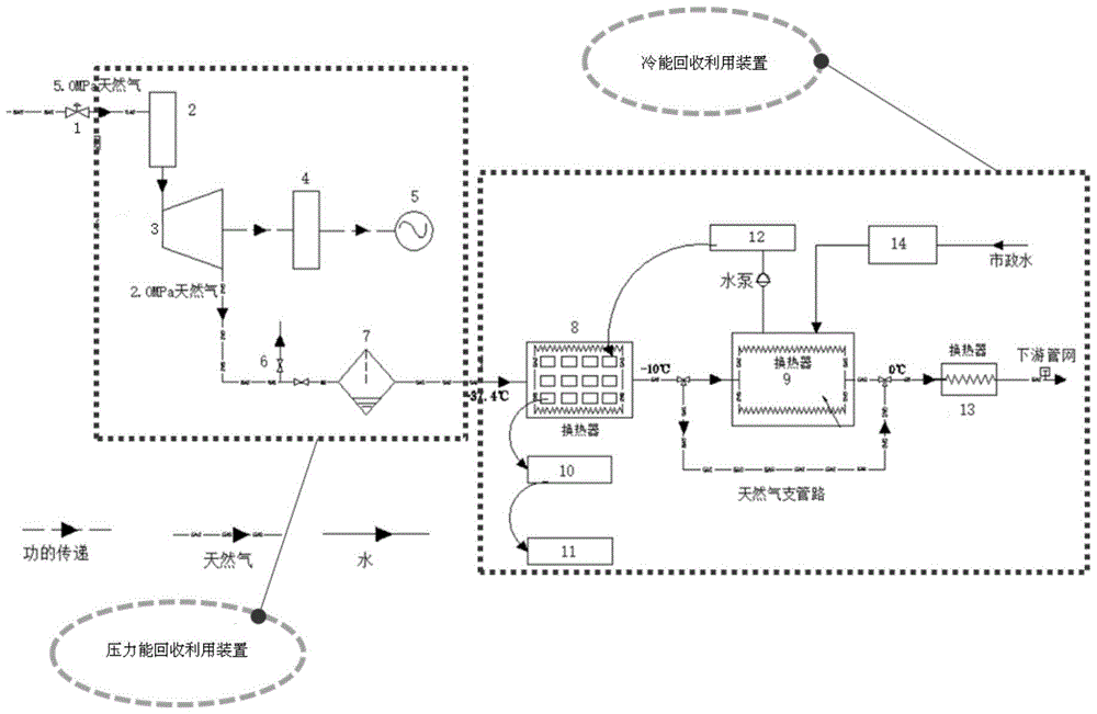
[0041] The following is an example of a utilization system for the recovery of natural gas pressure energy and cold energy from 5MPa to 2MPa pipeline network. figure 1 As shown, the device mainly includes: regulator valve 1, dehydrator 2, expander 3, transmission assembly 4, generator 5, vent pipeline 6, gas-liquid separator 7, salt water pool 8, water storage tank 9, ice melting Tank 10, cold storage 11, ice bucket 12, electric heater 13 and solar heat collector 14.

[0042] A first heat exchanger is arranged in the brine pool, and a second heat exchanger is arranged in the water storage tank. Wherein, the tube of the first heat exchanger is low-temperature natural gas, the outside of the tube is brine (about -10°C), the tube of the second heat exchanger is low-temperature natural gas, and the tube of the second heat exchanger is a water bath of about 5°C; the electric heater 13 is normally off The state electric heater is not working. When the outlet temperature of the wate...


PUM


Abstract

The invention relates to an efficient pipe network natural gas pressure energy and cold energy recycling and utilization system. The system is used for recycling natural gas pressure energy in a high-pressure natural gas pipe to be used for generating electricity and recycling natural gas cold energy in a pipe network to be used for making ice. The system comprises a pressure energy recycling device and a cold energy recycling device. The pressure energy recycling device is connected with the cold energy recycling device and the high-pressure natural gas pipe. The cold energy recycling device is connected with a downstream natural gas pipe and the municipal water pipe network. A pressure stabilizing valve is arranged between the high-pressure natural gas pipe and the pressure energy recycling device. Compared with the prior art, the efficient pipe network natural gas pressure energy and cold energy recycling and utilization system has the advantages of being high in energy utilization rate, safe, reliable, capable of achieving multi-temperature-return protection, efficient, capable of saving energy, clear in structure, convenient to remold and the like.

Description

technical field [0001] The invention relates to the field of recovery and utilization of pressure energy and cold energy in the natural gas pressure regulation process, in particular to a utilization system for recovering pressure energy and cold energy of natural gas in a pipeline network. Background technique [0002] Natural gas is a clean energy. With the adjustment of the national energy structure, the proportion of natural gas consumption is increasing. By 2020, the proportion of natural gas in primary energy consumption will increase to more than 10%, and my country's natural gas pipeline will be developed rapidly. [0003] Long-distance natural gas pipelines generally use high-pressure transmission, that is, during the transportation process, natural gas needs to be raised to high-pressure transmission through the compressor station, and needs to be depressurized at the user side. At present, the pipeline pressure of Line I of the "West-to-East Gas Pipeline" that has...

Claims


Application Information

Patent Timeline
Patent Type & Authority Patents(China)
IPC IPC(8): F01D15/10F01K17/06F25C1/00
CPCY02P60/85
Inventor 李琦芬杨涌文刘晓婧张涛徐晶晶梁晓雨候宗钦
Owner 茂盟(上海)工程技术股份有限公司
Why Eureka
Try Eureka