
Waste heat recycling air preheating bypass coal saving system and application thereof

A technology of air preheating and waste heat recovery, applied in the direction of reducing greenhouse gases, climate sustainability, lighting and heating equipment, etc., can solve the problem that the repair effect is difficult to achieve the ideal effect, affect the continuous production requirements of enterprises, tube sheets or welds No leakage and other problems, to achieve the effect of no safety hazard, simple and convenient operation, and reduce pollution

Inactive Publication Date: 2015-08-26
JIANGSU JINYUAN TENGFENG HEAT EXCHANGE EQUIP CO LTD
View PDF0 Cites 5 Cited by
  • Summary
  • Abstract
  • Description
  • Claims
  • Application Information

AI Technical Summary

Problems solved by technology

[0003] The waste flue gas in the waste heat recovery equipment often contains sulfur dioxide and other components. When encountering steam or moisture, it will form sulfurous acid substances, which will corrode the tube sheets and welds, resulting in leakage at the tube sheets or welds, which seriously affects the company's profitability. Continuous production requirements
In view of the above problems, traditional methods such as argon arc welding have a long maintenance period and high cost, and the service life after maintenance is often short, so the repair effect is difficult to achieve the desired effect

Method used


Image

  • Waste heat recycling air preheating bypass coal saving system and application thereof

Examples


Embodiment 1

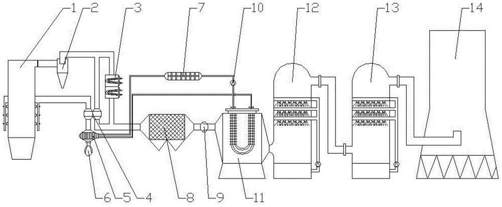
[0026] This embodiment provides a waste heat recovery air preheating bypass coal-saving system, the structure is as follows figure 1 As shown, it includes a boiler 1, a spray tower and a cooling tower 14. The exhaust gas outlet of the boiler 1 is connected to the air inlet of the cyclone dust collector 2, and the gas outlet of the cyclone dust collector 2 is connected to the heat pipe of the heat exchanger 4, and the cyclone dust collector 2 The outlet of the outlet is provided with a branch to connect the decompression device 3, and the decompression device 3 is connected in series with the heat pipe of the heat exchanger 4;

[0027] The heat pipe outlet of the heat exchanger 4 is connected to the air inlet of the electrostatic precipitator 8, and the air outlet of the electrostatic precipitator 8 is provided with a second fan 9, and the air outlet of the second fan 9 is connected to the exhaust gas cooler 11, and the upper end of the exhaust gas cooler 11 is There are two ci...

Embodiment 2

[0037] This embodiment provides a waste heat recovery air preheating bypass coal-saving system, the structure is as follows figure 1 As shown, it includes a boiler 1, a spray tower and a cooling tower 14. The exhaust gas outlet of the boiler 1 is connected to the air inlet of the cyclone dust collector 2, and the gas outlet of the cyclone dust collector 2 is connected to the heat pipe of the heat exchanger 4, and the cyclone dust collector 2 The outlet of the outlet is provided with a branch to connect the decompression device 3, and the decompression device 3 is connected in series with the heat pipe of the heat exchanger 4;

[0038] The heat pipe outlet of the heat exchanger 4 is connected to the air inlet of the electrostatic precipitator 8, and the air outlet of the electrostatic precipitator 8 is provided with a second fan 9, and the air outlet of the second fan 9 is connected to the exhaust gas cooler 11, and the upper end of the exhaust gas cooler 11 is There are two circ...


PUM


Abstract

The invention discloses a waste heat recycling air preheating bypass coal saving system and application thereof. A waste gas outlet of a boiler is connected with a gas inlet of a cyclone dust collector, a gas outlet of the cyclone dust collector is connected with a heat pipe of a heat exchanger, a branch is arranged at an opening of the cyclone dust collector and connected with a decompressor, and the decompressor is connected with the heat pipe of the heat exchanger in series. A heat pipe outlet of the heat exchanger is connected with a gas inlet of an electrostatic dust collector. A gas outlet of the electrostatic dust collector is provided with a second draught fan. A gas outlet of the second draught fan is connected with a waste gas cooler. The upper end of the waste gas cooler is provided with two circular ventilation holes. A circular gas outlet is provided with a sucking pump. The other end of the sucking pump is connected with a second preheater. A gas outlet of the second preheater is connected with a gas inlet of a first preheater. A gas outlet of the first preheater is connected with a circular gas inlet of the waste gas cooler to form a loop. The waste heat recycling air preheating bypass coal saving system is reasonable in design, easy and convenient to operate, high in preheat recycling rate, low in operation cost, capable of saving energy and protecting the environment and free of pollution to the air.

Description

technical field [0001] The invention belongs to the technical field of energy reuse, in particular to a waste heat recovery air preheating bypass coal-saving system and its application. Background technique [0002] Waste heat refers to the sensible heat and latent heat that have not been rationally utilized in the original design in the energy-consuming devices of industrial enterprises that have been put into operation due to the limitations of history, technology, ideas and other factors. It includes waste heat of high-temperature exhaust gas, waste heat of cooling medium, waste heat of waste steam and waste water, waste heat of high-temperature products and slag, waste heat of chemical reaction, waste heat of combustible waste gas and liquid, waste heat, etc. According to the survey, the total waste heat resources of various industries account for about 17%-67% of their total fuel consumption, and the recyclable waste heat resources are about 60% of the total waste heat ...

Claims


Application Information

Patent Timeline
Patent Type & Authority Applications(China)
IPC IPC(8): F23J15/04F23J15/06
CPCY02E20/30
Inventor 李明祥朱冬宏陈道祥
Owner JIANGSU JINYUAN TENGFENG HEAT EXCHANGE EQUIP CO LTD
Learn More