
Coal gasification spray gun

A coal gasification and spray gun technology, applied in electrical components, plasma and other directions, can solve the problems of loose cathode, easy leakage of cooling water, displacement and sealing of cathode, etc., to meet application requirements and improve the effect of pyrolysis capacity

Active Publication Date: 2015-08-26
JINING XINRUIDA INFORMATION TECH CO LTD
View PDF9 Cites 3 Cited by
  • Summary
  • Abstract
  • Description
  • Claims
  • Application Information

AI Technical Summary

Problems solved by technology

In this patent, water vapor is sprayed into the discharge area in the contraction chamber through the nozzle at the center of the cathode head end, so that the heat absorbed by the water vapor into the cathode head end is preheated, and at the same time, it has a cooling effect on the cathode head end, which overcomes the conventional plasma spray gun Disadvantages of easy ablation of electrodes
However, since this patent is to take the measure of "the head end side wall of the cathode is tightly fitted in the front wall of the cathode base central axis, and the tail end of the cathode is tightly fitted in the wall of the cathode base rear end" to carry out the water jacket Sealed, the thermal expansion and contraction of the material will loosen the cathode, resulting in displacement of the cathode and unreliable sealing. The cooling water in the water jacket is easy to leak into the discharge area in the shrinkage cavity, which affects the normal operation of the spray gun.

Method used


Image

  • Coal gasification spray gun
  • Coal gasification spray gun
  • Coal gasification spray gun

Examples


Embodiment 1

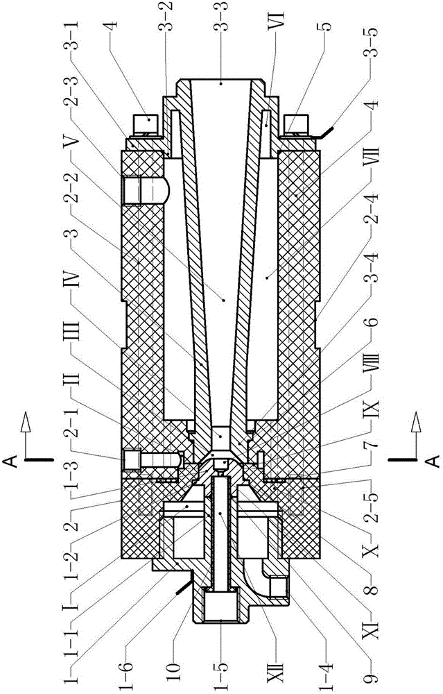
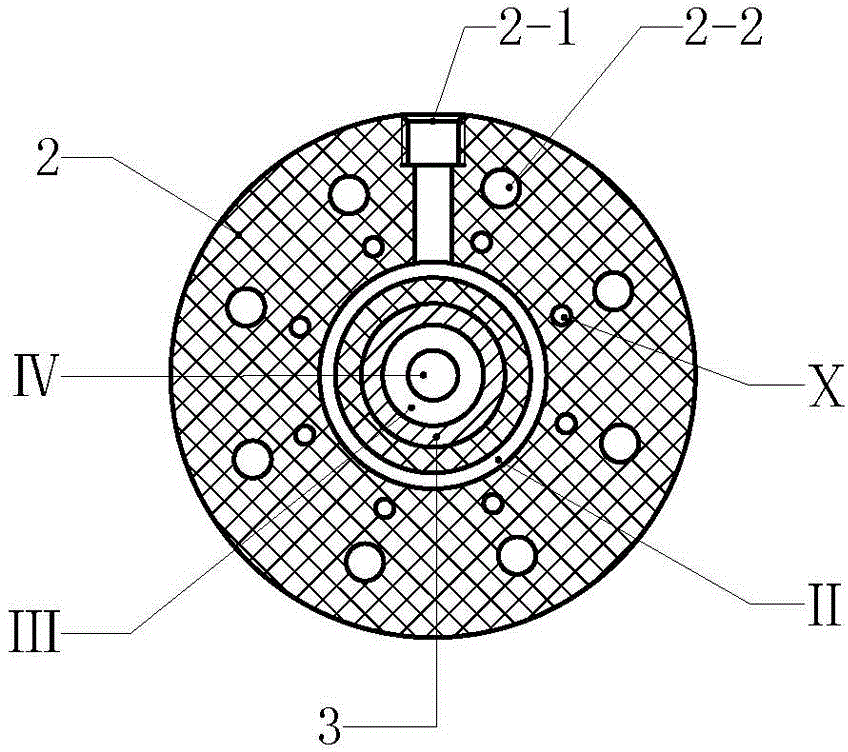
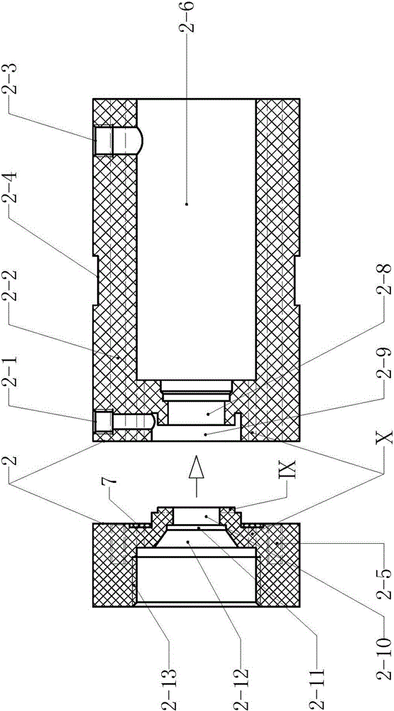
[0021] Example 1 figure 1 with image 3 In the illustrated embodiment, a coal gasification spray gun is composed of an insulating gun frame 2, a cathode 1 and an anode 3. The insulating gun frame 2 is a hollow rotary structure, and the hollow rotary body of the insulating gun frame 2 has a rear cavity 2- 12. The middle cavity 2-9 and the front cavity 2-6, the rear cavity 2-12, the middle cavity 2-9 and the front cavity 2-6 are arranged in sequence from the back to the front, and the back cavity 2-12 and the middle cavity 2-9 There is a sealing groove 2-11 and a via hole 2-10 between them, there is a tangential air groove Ⅸ on the front wall of the via hole 2-10, and there is a socket hole between the middle cavity 2-9 and the front cavity 2-6 2-8; there is a hollow connecting rod 1-1 on the cathode 1, and the inner space of the hollow connecting rod 1-1 constitutes the material channel Ⅻ, and the material channel Ⅻ is connected to the raw material input interface 1-5, which...


PUM


Abstract

The invention discloses a coal gasification spray gun, and relates to a plasma spray gun which comprises an insulating gun rack, a cathode and an anode, wherein the insulating gun rack comprises a rear cavity, a middle cavity and a front cavity; a via hole is formed between the rear and middle cavities; a socket hole is formed between the middle and front cavities; a through hole is formed in the axial center of a cathode head; a convex edge which protrudes towards the periphery is formed on the wall body of the cathode head; a tenon is arranged on the rear wall body of the anode; a positioning lug boss is arranged on the front wall body of the anode; the anode is mounted in the front cavity of the insulating gun rack; a bell mouth in the rear end of the anode enters the front cavity of the middle cavity; a cooling water jacket is defined by the space between the outer wall of the anode and the inner wall of the front cavity of the insulating gun rack; the cathode is mounted in the rear cavity of the insulating gun rack; the head end of the cathode head enters the bell mouth space in the rear end of the anode; a ring-shaped cooling cavity is defined by the space between the outer wall at the rear part of the cathode head and the inner wall of the rear cavity of the insulating gun rack. Through the adoption of the coal gasification spray gun, coal gasification can be quickly performed in the coal gasification spray gun, the gasification rate approaches 100%, and the application requirements for coal gasification production can be met.

Description

technical field [0001] The invention relates to plasma equipment, in particular to a plasma spray gun. Background technique [0002] At present, plasma technology has been widely used, industrially used in plasma ignition, plasma spraying, metal smelting, plasma heating to manufacture nanomaterials, cutting, waste incineration and waste treatment, etc. Plasma is a state formed by the phenomenon of ionizing discharge, with which active chemicals of excited atoms, excited molecules, dissociated atoms, free atomic groups, groups of atoms or molecular ions are generated and their collisions with other chemicals caused the reaction. In the plasma torch, the discharge effect causes the working gas molecules to lose the outer electrons and form an ion state, which generates high temperature through mutual collision. The center temperature of the plasma torch can be as high as tens of thousands of degrees Celsius, and the temperature of the edge of the torch can also reach thousand...

Claims


Application Information

Patent Timeline
IPC IPC(8): H05H1/42H05H1/28H05H1/34
Inventor 周开根
Owner JINING XINRUIDA INFORMATION TECH CO LTD
Learn More