An adsorption refrigeration device driven by engine exhaust gas

An adsorption refrigeration and engine technology, applied in the direction of refrigerators, refrigeration and liquefaction, machines using waste heat, etc., can solve problems such as air pollution, heat waste, and inability to meet the refrigeration needs of refrigerated vehicles, and achieve the goal of increasing the adsorption temperature and saving energy. Effect

Active Publication Date: 2015-09-09
SHANGHAI JIAO TONG UNIV +1
View PDF5 Cites 11 Cited by
  • Summary
  • Abstract
  • Description
  • Claims
  • Application Information

AI Technical Summary

Problems solved by technology

Considering that the engine exhaust has relatively high heat and high temperature, if the engine exhaust is discharged directly, it will inevitably lead to waste of heat, so an adsorption refrigeration device driven by automobile exhaust is proposed, such as figure 1 The shown set of zeolite-water adsorption air-conditioning system driven by the waste heat of diesel locomotive flue gas, the field operation shows that the adsorption waste heat air-conditioning system can basically meet the needs of air-conditioning in the cab of locomotives except for slow train conditions. The circulation mode achieves continuous cooling. For typical working conditions, the cooling capacity of the system is 3.0-4.2 kW, and the evaporation temperature is about 10°C. This system meets the air conditioning working conditions, but cannot meet the refrigeration working conditions, that is, i

Method used


Image

  • An adsorption refrigeration device driven by engine exhaust gas
  • An adsorption refrigeration device driven by engine exhaust gas
  • An adsorption refrigeration device driven by engine exhaust gas

Examples


Embodiment Construction

[0032] The invention will be described in more detail hereinafter with reference to the accompanying drawings showing embodiments of the invention. However, this invention may be embodied in many different forms and should not be construed as limited to the embodiments set forth herein. Rather, these embodiments are provided so that this disclosure will be thorough and complete, and will fully convey the scope of the invention to those skilled in the art. In these drawings, the size and relative sizes of layers and regions may be exaggerated for clarity.

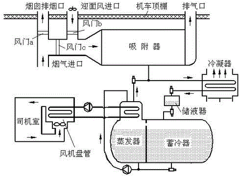
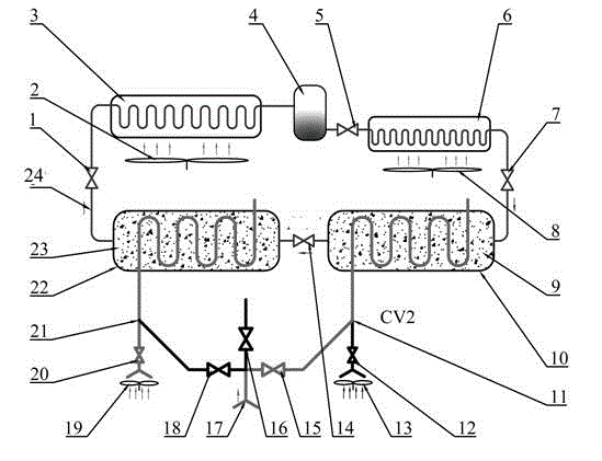
[0033] The present invention provides an adsorption refrigeration device driven by engine exhaust gas. The device is mainly designed for refrigerated vehicles and includes a condenser 3, an evaporator 6, a high-temperature salt adsorption bed 10, a medium-temperature salt adsorption bed 22 and other components; In the present invention, the tail gas produced by the engine of the refrigerated truck is used to heat the adsorb...


PUM


Abstract

The invention provides an adsorption refrigeration device driven by engine exhaust gas. The adsorption refrigeration device comprises a condenser, an evaporator, a high temperature salt adsorption bed and a medium temperature salt adsorption bed which are connected successively to form a refrigerant circulating flow loop. Finned tubes of the high temperature salt adsorption bed are filled with manganese chloride/sulfide expanded graphite composite adsorbents and finned tubes of the medium temperature salt adsorption bed is filled with calcium chloride/sulfide expanded graphite composite adsorbents. Engine exhaust gas is conveyed into the high temperature salt adsorption bed and the medium temperature salt adsorption bed via air and exhaust gas pipes and is discharged to the external environment after heat exchange with the finned tubes of the high temperature salt adsorption bed and the medium temperature salt adsorption bed. The air and exhaust pipes of the high temperature salt adsorption bed and the medium temperature salt adsorption bed lead to the external air through branches. The adsorption refrigeration device is suitable for refrigerator trucks; heat in the engine exhaust gas of the refrigeration trucks can be used for driving the adsorption refrigeration device to obtain cold energy and achieve a refrigerating effect. The adsorption refrigeration device is suitable for more severe working conditions.

Description

technical field [0001] The invention relates to the technical field of refrigeration, in particular to an adsorption refrigeration device driven by exhaust gas from an engine. Background technique [0002] Adsorption refrigeration, as a green and environmentally friendly technology that can be driven by low-grade heat energy (such as engine exhaust, geothermal energy, etc.), has attracted more and more attention from researchers. Adsorption refrigeration system is mainly composed of adsorption bed, evaporator and condenser. Adsorption refrigeration generally includes two processes: (1) cooling adsorption process, which uses cooling water or air to cool the adsorption bed, so that the adsorbent in the adsorption bed Adsorb the refrigerant in the evaporator, and the refrigerant evaporates in the evaporator to generate cold energy; (2) Heating and desorption process, which uses low-grade heat energy to regenerate the saturated adsorbent, that is, to separate the refrigerant fro...

Claims


Application Information

Patent Timeline
IPC IPC(8): F25B17/08F25B27/02
CPCY02A30/274Y02B30/625F25B17/083F25B27/02
Inventor 高鹏王丽伟张雪峰王如竹李道彭梁仲文江龙
Owner SHANGHAI JIAO TONG UNIV
Why Eureka
Try Eureka