Ultralow attenuation large-effective-area single-mode optical fiber

An effective area, single-mode optical fiber technology, applied in the direction of multi-layer core/clad optical fiber, clad optical fiber, light guide, etc., can solve the problems of unable to suppress the nonlinear effect of optical fiber, viscosity gradient mismatch, and increase optical fiber attenuation, etc. Achieve the effects of suppressing the fundamental mode cut-off problem, improving bending loss, and reducing the cut-off wavelength

Active Publication Date: 2015-09-09
SICHUAN LEFEI OPTOELECTRONICS TECH CO LTD
View PDF9 Cites 8 Cited by
  • Summary
  • Abstract
  • Description
  • Claims
  • Application Information

AI Technical Summary

Problems solved by technology

However, if in the design of ultra-low attenuation and large effective area optical fiber, especially in the ultra-low attenuation and large effective area optical fiber using pure silica material as the outer cladding, because the refractive index of the core layer is the same as that of the pure silica outer cladding The difference is not large, and the core diameter of the large effective area fiber design is generally very large, which is more likely to cause the most troublesome fundamental mode leakage in the fiber waveguide design, causing abnormal long-wavelength attenuation of the fiber
However, conventional solutions, such as increasing the volume of a single depressed cladding, will cause the cut-off wavelength of the fiber to exceed the standard. Therefore, finding a better design method for the depressed cladding is also the focus of achieving ultra-low attenuation and large effective area fiber design.
[0014] Second, consider viscosity matching: If there is no viscosity optimization design in the outer cladding material, its viscosity will not match the viscosity gradient of the inner cladding and core layers, which will also cause defects in the interface position and virtual temperature rise, thereby increasing the optical fiber attenuation
[0016] The document US8515231B2 proposes a single-mode optical fiber with a double depressed cladding structure, but the core rod is designed with high-concentration Ge doping, and the core layer diameter is small, so it cannot achieve ultra-low attenuation performance, and the effective area is obviously less than 100 μm 2 , can not suppress the nonlinear effect of the fiber

Method used


Image

  • Ultralow attenuation large-effective-area single-mode optical fiber
  • Ultralow attenuation large-effective-area single-mode optical fiber
  • Ultralow attenuation large-effective-area single-mode optical fiber

Examples


Embodiment Construction

[0044] The present invention is described in detail below in conjunction with the examples.

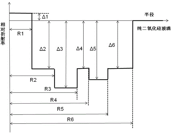
[0045] It includes a core layer and a cladding layer. The core layer is a silicon dioxide glass layer co-doped with germanium and fluorine, or a silicon dioxide glass layer doped with germanium. The core layer is covered with an inner cladding layer from inside to outside in sequence. A sunken inner cladding, an intermediate inner cladding, a second sunken inner cladding, an auxiliary outer cladding and an outer cladding. The standard diameter of the outer cladding is 125 μm.

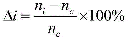
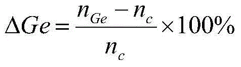
[0046] Table 1 lists the refractive index profile parameters of the preferred embodiment of the present invention, wherein ΔGe is the relative refractive index contribution of germanium doping in the core layer. Table 2 shows the optical transmission characteristics corresponding to the optical fibers described in Table 1.

[0047] Table 1, the optical fiber profile parameter of the embodiment of the present ...


PUM


Abstract

The present invention relates to an ultralow attenuation large-effective-area single-mode optical fiber. The ultralow attenuation large-effective-area single-mode optical fiber comprises a core layer and wrapping layers, and is characterized in that a radius R1 of the core layer is 4.5-6.5 [mu]m, [delta]1 of the core layer is -0.05% to 0.10%, the core layer is wrapped from inside to outside in turn by an inner wrapping layer, a first sunken inner wrapping layer, a middle inner wrapping layer, a second sunken inner wrapping layer, an auxiliary outer wrapping layer and an outer wrapping layer, a radius R3 of the inner wrapping layer is 8.5-14 [mu]m, [delta]2 is -0.35% to -0.12%, an radius R3 of the first sunken inner wrapping layer is 13-22[mu]m, [delta]3 is -0.7% to -0.30%, a radius R4 of the middle inner wrapping layer is 14-23[mu]m, [delta]4 is -0.40% to -0.15%, a radius R5 of the second sunken inner wrapping layer is 28-30 [mu]m, [delta]5 is -0.6% to -0.25%, a radius R6 of the auxiliary outer wrapping layer is 35-50[mu]m, [delta]6 is -0.55% to -0.15%, and the outer wrapping layer is a pure silicon dioxide glass layer. The ultralow attenuation large-effective-area single-mode optical fiber is low in attenuation and large in effective area, and has excellent bending loss and dispersion characteristics, and cabling cut-off wavelength is smaller than 1530 nm.

Description

technical field [0001] The invention relates to the technical field of optical fiber transmission, in particular to a single-mode optical fiber with ultra-low attenuation and large effective area. Background technique [0002] With the rapid growth of IP network data services, operators' demand for transmission capacity continues to increase, and the single-fiber capacity in the existing network is gradually approaching the limit value of 100Tbps. The 100G transmission system has entered the first year of commercial use. How to further increase the transmission capacity on the basis of 100G transmission signals is the focus of attention of various system equipment manufacturers and operators. [0003] In 100G and beyond 100G systems, the receiving end adopts coherent reception and digital signal processing technology (DSP), which can digitally compensate the dispersion and polarization mode dispersion (PMD) accumulated in the entire transmission process in the electrical do...

Claims


Application Information

Patent Timeline
Patent Type & Authority Applications(China)
IPC IPC(8): G02B6/036
CPCG02B6/03688
Inventor 张磊龙胜亚朱继红吴俊王瑞春
Owner SICHUAN LEFEI OPTOELECTRONICS TECH CO LTD
Why Eureka
Try Eureka