

Low-speed reluctance motor and manufacturing method thereof
A reluctance motor, low-speed technology, applied in the direction of magnetic circuit rotating parts, magnetic circuit static parts, manufacturing stator/rotor bodies, etc., can solve the problem of not being able to solve the requirements of low-speed and high-torque drive, and the high cost of motor manufacturing , maintenance costs and other issues, to achieve the effect of large torque, reduce maintenance costs, and improve utilization
- Summary
- Abstract
- Description
- Claims
- Application Information
AI Technical Summary
Problems solved by technology
Method used
Image

Examples
Embodiment 1
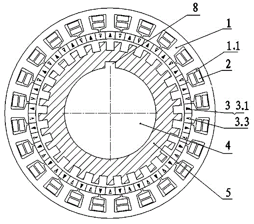
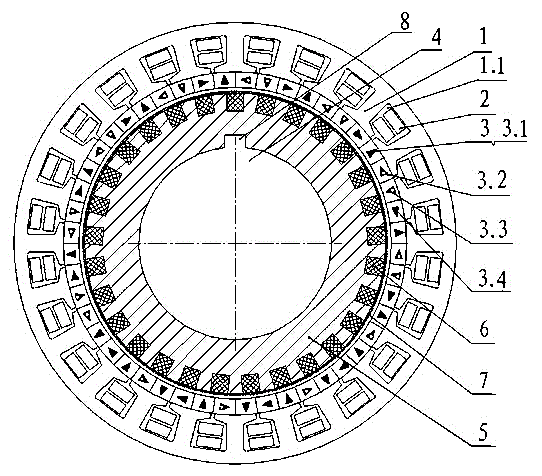
[0030] Example 1: It is the basic embodiment of the low-speed reluctance motor of the present invention. Such as figure 1 , 2 Shown, a kind of low-speed reluctance motor, it comprises frame, stator lamination iron core 1, stator field winding 2, field permanent magnet 3, rotating shaft 4 and laminated salient pole rotor 5; The number of pole pairs of described stator field winding 2 The number of pole pairs is not equal to that of the laminated salient pole rotor 5 ; the laminated salient pole rotor 5 runs at a fixed speed, which is less than the rotation speed of the magnetic field generated by the stator excitation winding 2 .
Embodiment 2
[0031] Example 2: It is a further embodiment on the basis of embodiment 1. In the low-speed reluctance motor, the stator field winding 2 is embedded in the slot 1.1 of the stator lamination core 1 . The excitation permanent magnet 3 is fixed in the dovetail groove on the inner surface of the stator lamination core 1 , or fixed on the inner surface of the stator lamination core 1 by glue connection. The laminated salient pole rotor 5 is made of laminated silicon steel sheets and has a plurality of salient poles, and the number of salient poles is even or odd. There is a filler 6 between the salient poles of the laminated salient pole rotor 5; the outer surface of the salient poles of the laminated salient pole rotor 5 is provided with a binding band 7 for increasing the fixed bonding strength between the filler 6 and the laminated salient pole rotor 5 . The filler 6 is a non-conductive and non-magnetic material, preferably a glass fiber composite material or a carbon fiber ...
Embodiment 3
[0032] Example 3: is a preferred embodiment. Such as figure 1 As shown, the low-speed reluctance motor is a radially magnetized high-torque low-speed reluctance motor, and its excitation permanent magnet 3 is a radial magnetic pole structure of radial magnetization, and the S pole excitation permanent magnet of radial magnetization 3.1 (see figure 1 The radial solid triangle with the middle acute angle facing away from the axis) and the radially magnetized N-pole excitation permanent magnet 3.3 (see figure 1 The radial hollow triangle with the middle acute angle pointing to the axis).
[0033] The stator laminated core 1 is composed of laminated silicon steel sheets, and is axially fixed with the buckle and the end pressure plate. The stator excitation winding 2 is wound with enamelled copper wire, and the winding is embedded in the slot 1.1 of the stator laminated core. Then vacuum pressure impregnation is used to insulate and dry the stator field winding. The excitatio...
PUM
 Abstract
Description
Claims
Application Information