Light path device and method for laser peening forming of large workpiece

A technology of laser peening forming and large workpieces, which is applied in the field of laser peening optical path device and laser peening forming, which can solve the problems of complex motion mechanism, difficult motion accuracy and not simple structure of the universal joint reflector, and reach the range of motion Small, simple movement, small space occupation effect

Active Publication Date: 2015-09-23
SHANGHAI JIAO TONG UNIV
View PDF9 Cites 16 Cited by
  • Summary
  • Abstract
  • Description
  • Claims
  • Application Information

AI Technical Summary

Problems solved by technology

However, its disadvantages are: first, the telescope system and the Stokes lens group in the light guide system are independent of each other, the number of lenses is large, and the composition is not simple; difficulty

Method used


Image

  • Light path device and method for laser peening forming of large workpiece
  • Light path device and method for laser peening forming of large workpiece
  • Light path device and method for laser peening forming of large workpiece

Examples


Embodiment

[0038] The workflow of the embodiment is as follows:

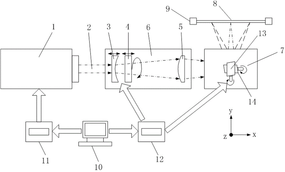
[0039] (1) First, the shot peening route is input on the computer 10 . At a certain moment in the scanning process, the coordinates of the scanning position on the forming workpiece 8 at this moment are determined according to the process path;

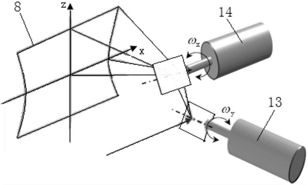
[0040] (2) The computer 10 calculates the appropriate poses of the first and second concave cylindrical lenses 3 and 4 and the x-direction scanning galvanometer 13 and the z-direction scanning galvanometer 14 according to the coordinates, and then controls the motion control card 12 to make the first, The second concave cylindrical lenses 3, 4 and the x-direction scanning galvanometer 13 and the z-direction scanning galvanometer 14 move to corresponding poses;

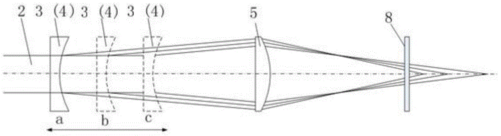
[0041] (3) The laser control card 11 controls the pulsed laser beam 2 to be emitted from the laser 1, first through the dynamic focusing and orthopedic system 6, the cross-sectional shape and focusing position of the puls...


PUM


Abstract

The invention discloses a light path device and method for laser peening forming of a large workpiece. The light path device comprises a laser device, a dynamic focusing and shape righting system, a scanning galvanometer system, the formed workpiece, a computer, a laser control card and a movement control card. The laser control card is connected with the laser device and is used for controlling starting of the laser device and various parameters of laser. The movement control card is connected with the dynamic focusing and shape righting system and the scanning galvanometer system. Both the laser control card and the movement control card are controlled by the computer. The dynamic focusing and shape righting system and the scanning galvanometer system are controlled by the computer to make corresponding movement after a specific shot blasting path is given, the shape of the section and the focusing position of a high-energy pulse laser beam are changed after the high-energy pulse laser beam emitted by the laser device passes through the dynamic focusing and shape righting system, and then the high-energy pulse laser beam points to a specific emergent direction after passing through the scanning galvanometer system, so that scanning and shot blasting on the large workpiece by laser are achieved through continuous movement of the dynamic focusing and shape righting system and the scanning galvanometer system.

Description

technical field [0001] The invention relates to the field of mechanical manufacturing, in particular to a laser shot peening optical path device and method based on a high-energy pulsed laser, which can be effectively applied to the laser shot peening of difficult-to-move large plates through laser scanning focusing and target surface spot correction. Background technique [0002] Large sheet forming has a wide range of applications in aerospace and defense, such as aircraft wings, skins, turbine engine blades, and more. In order for these large workpieces to work stably and efficiently in harsh environments, they are usually designed in a variety of complex shapes. In the production process, while satisfying their complex shapes, it is also necessary to ensure sufficient mechanical properties. [0003] For such panels, the traditional processing method is mechanical shot peening. This is a forming method that uses high-speed projectile flow to hit the metal surface, so th...

Claims


Application Information

Patent Timeline
Patent Type & Authority Applications(China)
IPC IPC(8): B21D26/00
Inventor 胡永祥余雄超姚振强李志
Owner SHANGHAI JIAO TONG UNIV
Why Eureka
Try Eureka