Self-powered wireless telemetering device for temperature of piston of internal combustion engine

A piston temperature and telemetry device technology, applied in the direction of measuring devices, electric devices, thermometers, etc., can solve the problems of needing or even more than 100 hours, unfavorable multi-channel reliability measurement, and taking out the memory in the plug, so as to avoid the difficulty of output leads , Guarantee the effect of sustainability and safe use

Inactive Publication Date: 2015-09-30
UNIV OF JINAN
View PDF8 Cites 12 Cited by
  • Summary
  • Abstract
  • Description
  • Claims
  • Application Information

AI Technical Summary

Problems solved by technology

The electromagnetic induction method and the infrared telemetry method rely on point-to-point transmission of signals, and can only obtain the temperature at the bottom dead center of the piston, which is not conducive to multi-channel reliability measurement
Storage method, which can continuously sample temperature data at any time under any working condition, but it is necessary to take out the memory from the piston when reading the data
In addition, the existing electric measurement methods all require battery or power supply, and the general battery life is about 4 hours, while the standard engine test takes even more than 100 hours, and the battery is installed in the inner cavity of the piston, which is difficult to replace
Moreover, at a high temperature of about 150 degrees, even if the battery performance is not damaged, it will be greatly weakened, and it is very dangerous to use the battery at high temperature
If an external power supply is used, the power leads will reciprocate rapidly with the piston, and the fatigue life will be extremely low

Method used


Image

  • Self-powered wireless telemetering device for temperature of piston of internal combustion engine
  • Self-powered wireless telemetering device for temperature of piston of internal combustion engine
  • Self-powered wireless telemetering device for temperature of piston of internal combustion engine

Examples


Embodiment Construction

[0021] In order to further explain the technical solution of the present invention, the present invention will be described in detail below through specific examples.

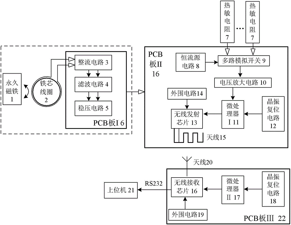
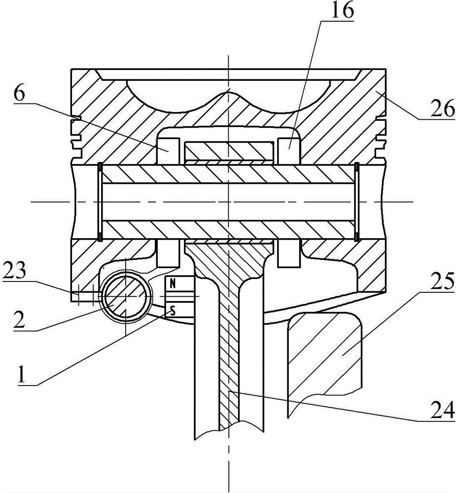
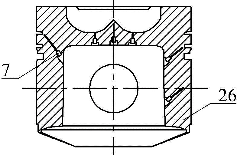
[0022] Such as figure 1 Shown is a self-powered wireless telemetry device for internal combustion engine piston temperature, which includes a power supply unit, a temperature signal acquisition unit, a wireless sending unit and a wireless receiving unit. The power supply unit includes a permanent magnet 1, an iron core coil 2 and a PCB board I6. The rectifier circuit 3, filter circuit 4 and voltage stabilizing circuit 5 are integrated in the PCB board I6. The iron core coil 2 is connected to the PCB board I6 through a high-temperature wire. The temperature signal acquisition unit includes a plurality of thermistors 7 , a multi-channel analog switch 8 , a constant current source circuit 9 , and a voltage amplification circuit 10 . The wireless transmitting unit includes a microprocessor I11, a crystal oscillato...


PUM


Abstract

The invention discloses a self-powered wireless telemetering device for the temperature of a piston of an internal combustion engine. The self-powered wireless telemetering device comprises a power supply unit, a temperature signal acquisition unit, a wireless transmitting unit and a wireless receiving unit, wherein the power supply unit mainly comprises an iron core coil fixed on the piston and a permanent magnet fixed on a connecting rod, the iron core coil and the permanent magnet reciprocate to generate induced voltage, and the power supply unit powers a follow-up measuring circuit continuously after voltage stabilization; the temperature signal acquisition unit transmits acquired temperature signals of multiple channels in the piston to the wireless transmitting unit fixed in an inner chamber of the piston, and the wireless transmitting unit transmits the temperature signals through radio waves to the wireless receiving unit fixed at the bottom of a crankcase. The self-powered wireless telemetering device is provided with the power supply unit, the whole device has lower power consumption, the measuring sustainability is guaranteed, and the problem of unreliability of a power supply battery in a high-speed reciprocating motion of the piston can be solved.

Description

technical field [0001] The invention relates to the technical field of internal combustion engine testing, in particular to a self-powered wireless measuring device for piston temperature. Background technique [0002] As the "heart" of the internal combustion engine, the piston is one of the most important components that convert the internal energy of high-temperature gas into internal combustion engine energy. Its working environment is the worst among internal combustion engine components. heat load. With the development of the engine towards high speed and strengthening, the boost ratio and specific power of the engine continue to increase, and the severe heat load becomes more and more prominent. In order to evaluate the thermal load of the piston, an intuitive and effective method is to analyze the temperature field of the piston. At present, the temperature field analysis of the piston mostly adopts finite element numerical simulation to obtain an approximate tempe...

Claims


Application Information

Patent Timeline
Patent Type & Authority Applications(China)
IPC IPC(8): G01K7/18
Inventor 葛荣雨米政杨海涛
Owner UNIV OF JINAN
Why Eureka
Try Eureka