Double-injection pump continuous injection device applicable to particle well drilling

An injection device and double-injection technology are applied in liquid/gas jet drilling, construction, etc., which can solve problems such as increasing the coverage of high-pressure areas and increasing safety risks

Inactive Publication Date: 2015-10-07
CCDC PETROLEUM CORING TECH
View PDF6 Cites 2 Cited by
  • Summary
  • Abstract
  • Description
  • Claims
  • Application Information

AI Technical Summary

Problems solved by technology

[0009] The particle impact drilling injection device disclosed in this patent document uses two sets of left and right identical and independent injection devices. Through alternate and repeated use, although continuous injection of particles is also realized, the coverage of the high-pressure area is greatly increased, and the security risk

Method used


Image

  • Double-injection pump continuous injection device applicable to particle well drilling
  • Double-injection pump continuous injection device applicable to particle well drilling
  • Double-injection pump continuous injection device applicable to particle well drilling

Examples


Embodiment 1

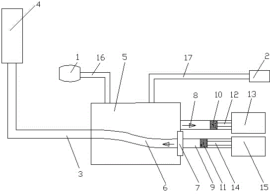
[0039] see figure 1 , a double injection pump continuous injection device suitable for particle drilling, including a slurry pump 1 and a screw conveyor 2, and also includes a particle mixing hopper 5 connected to the drilling riser 4 through a high-pressure pipeline 3, the particle mixing hopper 5 A reversing pipe 6 is arranged inside, and the reversing pipe 6 is connected with a swing hydraulic cylinder 7 that drives the reversing pipe 6 to swing left and right. The particle mixing hopper 5 is connected with a first conveying cylinder 8 and a second conveying cylinder 9. The first delivery cylinder 8 is provided with a first piston 10, the second delivery cylinder 9 is provided with a second piston 11, the first piston 10 is connected to the first hydraulic cylinder 13 through the first piston rod 12, and the second delivery cylinder 9 is connected to the first hydraulic cylinder 13. The piston 11 is connected to the second hydraulic cylinder 15 through the second piston rod...

Embodiment 2

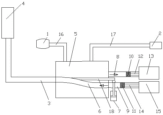
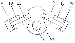
[0042] see figure 2 and image 3 , a double injection pump continuous injection device suitable for particle drilling, including a slurry pump 1 and a screw conveyor 2, and also includes a particle mixing hopper 5 connected to the drilling riser 4 through a high-pressure pipeline 3, the particle mixing hopper 5 A reversing pipe 6 is arranged inside, and the reversing pipe 6 is connected with a swing hydraulic cylinder 7 that drives the reversing pipe 6 to swing left and right. The particle mixing hopper 5 is connected with a first conveying cylinder 8 and a second conveying cylinder 9. The first delivery cylinder 8 is provided with a first piston 10, the second delivery cylinder 9 is provided with a second piston 11, the first piston 10 is connected to the first hydraulic cylinder 13 through the first piston rod 12, and the second delivery cylinder 9 is connected to the first hydraulic cylinder 13. The piston 11 is connected to the second hydraulic cylinder 15 through the se...

Embodiment 3

[0046] see image 3 and Figure 4 , a double injection pump continuous injection device suitable for particle drilling, including a slurry pump 1 and a screw conveyor 2, and also includes a particle mixing hopper 5 connected to the drilling riser 4 through a high-pressure pipeline 3, the particle mixing hopper 5 A reversing pipe 6 is arranged inside, and the reversing pipe 6 is connected with a swing hydraulic cylinder 7 that drives the reversing pipe 6 to swing left and right. The particle mixing hopper 5 is connected with a first conveying cylinder 8 and a second conveying cylinder 9. The first delivery cylinder 8 is provided with a first piston 10, the second delivery cylinder 9 is provided with a second piston 11, the first piston 10 is connected to the first hydraulic cylinder 13 through the first piston rod 12, and the second delivery cylinder 9 is connected to the first hydraulic cylinder 13. The piston 11 is connected to the second hydraulic cylinder 15 through the se...


PUM


Abstract

The invention discloses a double-injection pump continuous injection device applicable to particle well drilling, and belongs to the technical field of oil-gas drilling engineering. The double-injection pump continuous injection device comprises a particle mixing hopper. A reversing pipe is arranged inside the particle mixing hopper. A swing hydraulic cylinder is connected to the reversing pipe. A first conveying cylinder and a second conveying cylinder are connected to the particle mixing hopper. A first piston is arranged inside the first conveying cylinder. A second piston is arranged inside the second conveying cylinder. The first piston is connected to the first hydraulic cylinder through a first piston rod. The second piston is connected to the second hydraulic cylinder through a second piston rod. One end of the reversing pipe is communicated with a high-pressure pipeline, and the other end of the reversing pipe is communicated with the first conveying cylinder or the second conveying cylinder. A slurry pump is communicated with the particle mixing hopper through a first pipeline. A screw conveyor is communicated with the particle hopper through a second pipeline. According to the double-injection pump continuous injection device, injection continuity of particles into a well can be ensured, the working efficiency of particle impact drilling is effectively improved, the high-pressure area coverage range is small, and safety risk is lowered.

Description

technical field [0001] The invention relates to the technical field of oil and gas drilling engineering, in particular to a continuous injection device with double injection pumps suitable for particle drilling. Background technique [0002] The current conventional drilling technology is to use the drilling pressure and rotation of the drill bit at the bottom of the hole to break the rock mechanically to achieve the purpose of drilling. In this way, when encountering deep hard formations and strong abrasive formations, only the mechanical action of the drill bit is used to break the rocks. However, the function of the mud is only to carry cuttings, and the joint rock-breaking effect of hydraulic power and machinery cannot be realized, and there are problems of slow drilling speed, long cycle time and high cost. [0003] In recent years, particle impact drilling technology has been widely used as a revolutionary speed-increasing technology; particle impact drilling is a meth...

Claims


Application Information

Patent Timeline
Patent Type & Authority Applications(China)
IPC IPC(8): E21B7/18E21B21/01
Inventor 李伟成姚建林陈晓彬陈立黄伟胡畔冯明何超
Owner CCDC PETROLEUM CORING TECH
Why Eureka
Try Eureka