Energy-saving emission reduction system and energy-saving emission reduction method of horizontal type phase change heat exchanger and front-arrangement type water medium type GGH combined
A phase-change heat exchanger, energy-saving and emission-reducing technology, which is applied in combustion methods, air heaters, feed water heaters, etc., can solve the problems of increasing equipment costs, reducing equipment service life, and large heat transfer area. The effect of coal consumption for power generation, reduction of pollutant emissions, and simple control system
- Summary
- Abstract
- Description
- Claims
- Application Information
AI Technical Summary
Problems solved by technology
Method used
Image

Examples
Embodiment Construction
[0024] The present invention will be further described in detail below in conjunction with the accompanying drawings and examples. The following examples are explanations of the present invention and the present invention is not limited to the following examples.
[0025] Example.
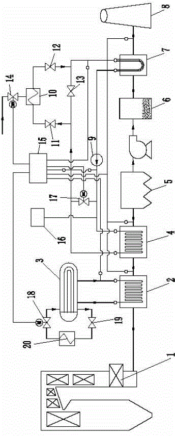
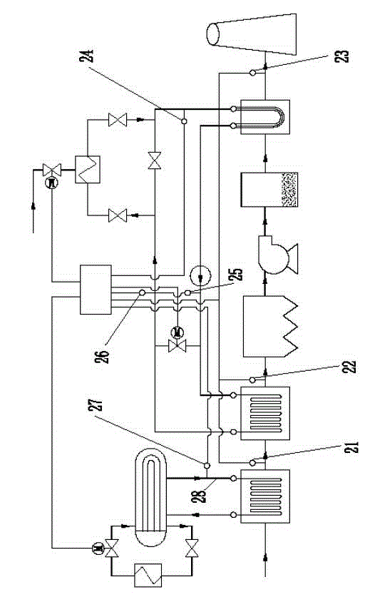
[0026] see Figure 1 to Figure 2 In this embodiment, the energy-saving and emission-reduction system combining the horizontal phase-change heat exchanger and the front-mounted water-medium GGH includes an air preheater 1, a phase-change heat exchanger 2, a phase-change hot steam drum 3, a low-low temperature Flue gas cooler 4, electrostatic precipitator 5, desulfurization tower 6, net flue gas reheater 7, chimney 8, heat medium water circulation pump 9, steam auxiliary heater 10, steam auxiliary heater heat medium water inlet valve 11, steam Auxiliary heater heat medium water outlet valve 12, steam auxiliary heater heat medium water bypass valve 13, steam volume regulating valve 14, terminal contr...
PUM
 Abstract
Description
Claims
Application Information
 - R&D
- Intellectual Property
- Life Sciences
- Materials
- Tech Scout
- Unparalleled Data Quality
- Higher Quality Content
- 60% Fewer Hallucinations
Browse by: Latest US Patents, China's latest patents, Technical Efficacy Thesaurus, Application Domain, Technology Topic, Popular Technical Reports.
© 2025 PatSnap. All rights reserved.Legal|Privacy policy|Modern Slavery Act Transparency Statement|Sitemap|About US| Contact US: help@patsnap.com