LED drive module with detuning compensation, drive circuit and working method

A technology of driving modules and working methods, which is applied in the direction of electric lamp circuit layout, electric light sources, lighting devices, etc., can solve problems such as easy misadjustment of LED driving modules, and achieve the effects of improving work efficiency, increasing switching speed, and optimizing driving circuits

Inactive Publication Date: 2015-10-07
CHANGZHOU TOPIC SEMICON TECH
View PDF9 Cites 9 Cited by
  • Summary
  • Abstract
  • Description
  • Claims
  • Application Information

AI Technical Summary

Problems solved by technology

[0005] The purpose of the present invention is to provide an LED driver module and its working method, to solve the technical problem that the LED driver module is easy to get out of adjustment, so as to limit the switching speed of the LED

Method used


Image

  • LED drive module with detuning compensation, drive circuit and working method
  • LED drive module with detuning compensation, drive circuit and working method
  • LED drive module with detuning compensation, drive circuit and working method

Examples


Embodiment 1

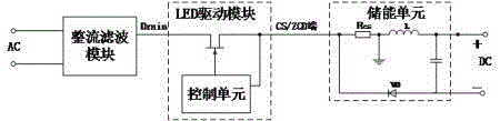
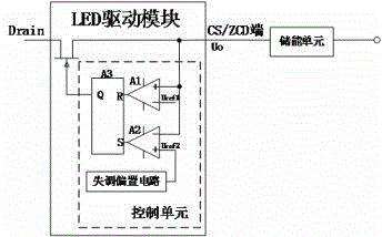
[0024] Such as Figure 1 to Figure 4 As shown, an LED drive module of the present invention includes: a power switch tube, the power switch tube is controlled by a control unit to be turned on or off, and the LED drive module is provided with a time-division multiplexing terminal, namely CS / ZCD terminal; when the time-division multiplexing terminal is used as the CS terminal, if the CS level is greater than a set upper limit value Uref1, the control unit is suitable for closing the power switch tube, or as the ZCD terminal, if the ZCD level is lower than a set lower limit value Uref2, the control unit is suitable for turning on the power switch tube; and an offset bias circuit is also provided in the control unit, and the offset bias circuit generates an offset voltage to correct the lower limit. Wherein the offset bias circuit is provided with a reference voltage source with a fixed output, and the output voltage source of the reference voltage source, that is, the offset vo...

Embodiment 2

[0038] On the basis of Embodiment 1, the present invention also provides a working method of the LED driving module, the LED driving module is provided with a time-division multiplexing terminal, that is, a CS / ZCD terminal; the working method, that is, when the dividing When the multiplexing terminal is used as the CS terminal, if the CS level is greater than a set upper limit value Uref1, the power switch tube will be turned off, or when used as the ZCD terminal, if the ZCD level is lower than a set lower limit value Uref2, it will be turned on a power switch tube; and correcting the lower limit value through the offset voltage.

Embodiment 3

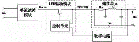
[0040] In Embodiment 1, the present invention also provides a driving circuit of an LED driving module, including: an energy storage unit, which is sequentially connected by a resistor Rcs, an energy storage inductor, an output capacitor and a freewheeling diode, and constitutes a loop, and the CS / ZCD end is connected to one end of the resistor Rcs to collect the CS level or ZCD level, and the other end of the resistor Rcs is grounded; the output end of the energy storage unit is connected to a sampling circuit, and the sampling The circuit is suitable for connecting the feedback voltage to the LED driving module to correct the lower limit value.


PUM


Abstract

The invention relates to an LED drive module with detuning compensation, a drive circuit and a working method. The LED drive module comprises a power switching tube which is controlled by a control unit. The LED drive module is provided with a time-sharing multiplexing end, i.e. a CS/ACD end. The control unit is suitable for turning off the power switching tube if CS level is greater than a preset upper limit value when the time-sharing multiplexing end acts as the CS end, or turning on the power switching tube if ZCD level is less than a preset lower limit value when the time-sharing multiplexing end acts as the ZCD end. The control unit is also internally provided with a detuning bias circuit which generates detuning voltage to correct the lower limit value. Time-sharing control of the power switching tube is realized via the time-sharing multiplexing end of the LED drive module so that the LED drive module is enabled to be more concise; besides, the lower limit value is corrected via detuning voltage so that change of the ZCD level and the power switching tube are enabled to be synchronized, and switching speed of the LED drive module is enhanced.

Description

technical field [0001] The invention relates to the field of LED drive power supply, in particular to an LED drive module with offset compensation, a drive circuit and a working method. Background technique [0002] With the development of LED technology, LED lamps are more and more widely used in low-brightness lighting and even in daily life due to their advantages of environmental protection and energy saving, low power consumption, and long service life. LEDs need to work in low-voltage DC state , when the mains power supply is used, it must be rectified into direct current, and then the LED working current and voltage are provided by the switching regulated power supply. [0003] There is an operational amplifier in the LED driving module, and because the slew rate of the operational amplifier is limited, its corresponding speed is limited, and then the switching speed of the LED is limited due to the loss of adjustment. [0004] Therefore, how to overcome this technic...

Claims


Application Information

Patent Timeline
Patent Type & Authority Applications(China)
IPC IPC(8): H05B37/02
CPCY02B20/40
Inventor 张永良
Owner CHANGZHOU TOPIC SEMICON TECH
Why Eureka
Try Eureka