

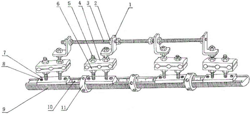
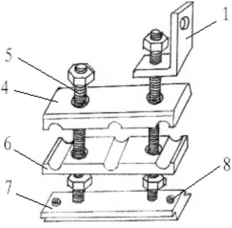
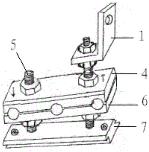
Unilateral two-arm adjustable two-way dual-power bone lengthening pressurized locking external fixator
An external fixator and dual-power technology, which is applied in the field of bone extension external fixator, unilateral double-arm adjustable bidirectional dual-power bone extension compression locking external fixator, can solve the problems of large space occupation, difficult needle penetration, and physiological problems. Anatomical inconsistencies and other issues, to achieve the effect of small space, easy care, and easy to carry
- Summary
- Abstract
- Description
- Claims
- Application Information
AI Technical Summary
Problems solved by technology
Method used
Image

Examples
Embodiment Construction
[0060] Exemplary embodiments of the present invention will be described below with reference to the accompanying drawings. In the interest of clarity and conciseness, not all features of an actual implementation are described in this specification. It should be understood, however, that in developing any such practical embodiment, many implementation-specific decisions must be made in order to achieve the developer's specific goals, such as meeting those constraints related to the system and business, and those Restrictions may vary from implementation to implementation. Furthermore, it should be understood that development work, while potentially complex and time-consuming, would be a routine undertaking for those skilled in the art having the benefit of this disclosure.
[0061] Here, it should also be noted that, in order to avoid obscuring the present invention due to unnecessary details, only the device structure and / or processing steps closely related to the solution ac...
PUM
 Abstract
Description
Claims
Application Information