Light guide plate, printing ink, and manufacturing method for ink-jet printing light guide plate

A technology of inkjet printing and manufacturing methods, which is applied in the direction of light guides, optics, optical components, etc., can solve the problems of long manufacturing cycle of embossed abrasive tools, high input-output ratio, and general processing efficiency, so as to improve the light guide effect, Small loss of light effect, strong reflection and diffusion performance

Active Publication Date: 2015-10-21
创联胜光电(广东)有限公司
View PDF8 Cites 7 Cited by
  • Summary
  • Abstract
  • Description
  • Claims
  • Application Information

AI Technical Summary

Problems solved by technology

[0002] At present, the methods of making light guide plate dots used in LCD TVs and flat lighting include ink screen printing, thermal embossing, and laser dotting. However, traditional screen printing has a low yield rate when processing plates below 2mm and products above 55", and is far away from light. The picture on the side appears yellow (mainly caused by the absorption of blue light by the existing ink), and the investment in environmental protection is large, and the processing cost is high
The main disadvantage of laser dotting is low processing efficiency and high input-output ratio, which is more suitable for large-scale processing
The processing cost of hot embossing dots is low, and the whole process is green and pollution-free production, but there are problems such as long manufacturing cycle of embossing abrasive tools, high production cost, and general processing efficiency, and it is suitable for large-scale production of a single variety, and the size is limited to Within 50〞

Method used


Image

  • Light guide plate, printing ink, and manufacturing method for ink-jet printing light guide plate
  • Light guide plate, printing ink, and manufacturing method for ink-jet printing light guide plate
  • Light guide plate, printing ink, and manufacturing method for ink-jet printing light guide plate

Examples


Embodiment Construction

[0022] Embodiments of the present invention will be described in detail below. It should be emphasized that the following description is only exemplary and not intended to limit the scope of the invention and its application.

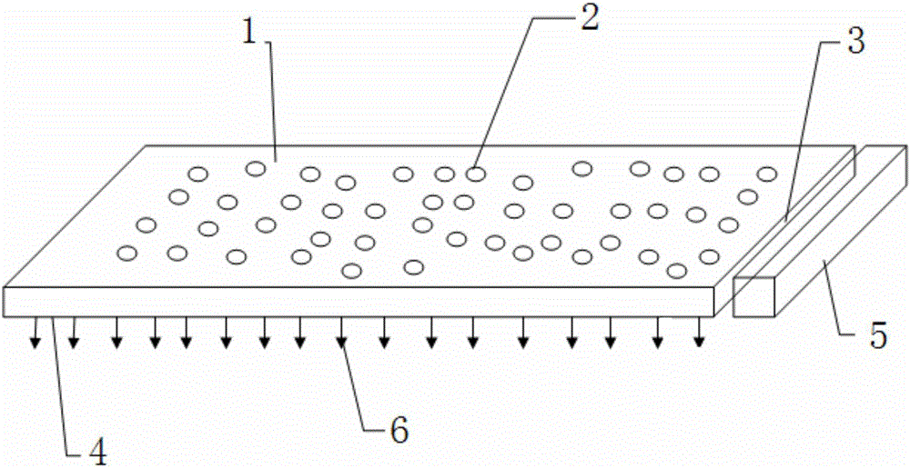
[0023] refer to figure 1 , in some embodiments, a light guide plate has a light incident surface 3, a light exit surface 4 and a dot surface 1, an LED light bar 5 is arranged outside the light incident surface 3, the light incident surface is located on the side of the light guide plate, and the light exit surface The face and the dot face are arranged oppositely, and the dots 2 of some printing inks are formed on the dot face to form an array ( figure 1 The dot distribution in is only schematic), the light incident from the light incident surface 3 is reflected, refracted and diffused by the dots 2 on the dot surface 1, and the uniform outgoing light 6 is emitted from the light exit surface 4. According to an embodiment of the present invention, the ...


PUM


Abstract

The invention discloses a light guide plate and a manufacturing method for an ink-jet printing light guide plate. The light guide plate is provided with a light incoming surface, a light outgoing surface, and a lattice point surface. The light incoming surface is located on a side surface of the light guide plate, and the light outgoing surface is opposite to the lattice point surface. The lattice point surface is provided with an array composed of a plurality of ink printing lattice points, and the intervals among the lattice points decrease along with the increases of the distances from the lattice points to the light incoming surface of the light guide plate. The sizes of all lattice points remain unchanged, or the sizes of all lattice points increase along with the increase of the distances from the lattice points to the light incoming surface of the light guide plate and the intervals among the lattice points remain unchanged. The invention also discloses printing ink for the lattice ink-jet printing of the light guide plate, and particles of the printing ink comprise PMMA or an organosilicone microballoon wrapping layer, and titanium oxide or calcium carbonate nano solid sphere particles wrapped by the PMMA or an organosilicone microballoon wrapping layer. According to the invention, the optical effect and machining efficiency of the light guide plate can be optimized.

Description

technical field [0001] The invention relates to a light guide plate, an ink and a method for making the light guide plate for inkjet printing. Background technique [0002] At present, the methods of making light guide plate dots used in LCD TVs and flat lighting include ink screen printing, thermal embossing, and laser dotting. However, traditional screen printing has a low yield rate when processing plates below 2mm and products above 55", and is far away from light. The side screen appears yellow (mainly caused by the existing ink absorbing blue light), and the investment in environmental protection is large, and the processing cost is high. The main disadvantage of the laser dotting method is low processing efficiency and high input-output ratio, which is more suitable for large-scale processing. The embossing dot process has low processing cost, and the whole process is green and pollution-free production, but there are problems such as long manufacturing cycle of embos...

Claims


Application Information

Patent Timeline
Patent Type & Authority Applications(China)
IPC IPC(8): G02B6/00
CPCG02B6/0043G02B6/0065
Inventor 贺孝林华路贺顺清郭爱理
Owner 创联胜光电(广东)有限公司
Why Eureka
Try Eureka