Nano-structure electrode for energy storage device and pseudocapacitor having electrode

An energy storage device and nanostructure technology, which is applied in the field of pseudocapacitors and nanostructure electrodes, can solve the problems of low surface area utilization rate and difficulty in reaching the ideal level of FP actual capacity, and achieve the effect of improving utilization rate and capacity

Inactive Publication Date: 2015-11-04
GUANG ZHOU NEW VISION OPTO ELECTRONICS TECH
View PDF1 Cites 9 Cited by
  • Summary
  • Abstract
  • Description
  • Claims
  • Application Information

AI Technical Summary

Problems solved by technology

Theoretically, the capacity of FP can reach 10 to 100 times that of ELDC, but the surface area of ​​the metal or metal oxide material electrode itself is difficult to compare with the loose and porous carbon material electrode, and the surface area utilization rate is low, resulting in the actual capacity of FP is also difficult. reach the ideal level
[0007] Therefore, in view of the defects of the conductive properties of...

Method used


Image

  • Nano-structure electrode for energy storage device and pseudocapacitor having electrode
  • Nano-structure electrode for energy storage device and pseudocapacitor having electrode
  • Nano-structure electrode for energy storage device and pseudocapacitor having electrode

Examples


Embodiment 1

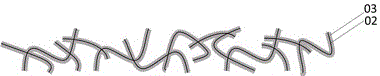
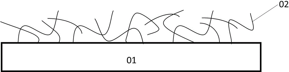
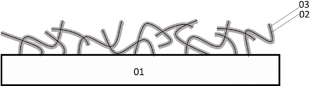
[0046] A nanostructured electrode for energy storage devices such as figure 1 As shown, there is an extraction electrode with interconnected metal nanostructures, and the surface of the extraction electrode is coated with an active layer 03 .

[0047] Specifically, the lead-out electrodes are metal nanowires 02 . The metal nanowire 02 has a diameter of 5 nm to 500 nm and a length greater than 5 um.

[0048] Specifically, the thickness of the active layer 03 is set to 1m~1000 nm, the active layer 03 can be formed by stacking one or more sub-active layers, and the material of each sub-active layer is transition metal oxide, conductive polymer Or any of the composite pseudocapacitive materials.

[0049] Among them, the transition metal oxide as the sub-active layer is specifically RuO 2 , MnO 2 、In 2 o 3 、MoO 3 , CuO, V 2 o 5 or TiO 2 any one or a combination of more than one.

[0050] The conductive polymer used as the sub-active layer is specifically polyaniline (PANi)...

Embodiment 2

[0062] A nanostructured electrode for energy storage devices such as Image 6 As shown, other structures are the same as those in Example 1, except that the nanostructure electrode is also provided with a modification layer 04, and the modification layer 04 is arranged between the surface of the lead-out electrode and the active layer 03. The modification layer can reduce the contact barrier between the active layer and the electrode surface and improve the charge transport efficiency.

[0063] The thickness of the modification layer 04 is 0.1 nm-10 nm. Specifically, the modification layer 04 is formed by stacking one or more sub-modification layers, and the material of the sub-modification layer is metal oxide, metal nitride or metal fluoride, specifically including: MgO, ZnO, CsO, TiN, MoN, LiF or CsF.

[0064] The nanoelectrode is prepared by the following steps:

[0065] (1) The metal nanowire 02 film is prepared on the flexible substrate 01 by using the solution proces...

Embodiment 3

[0074] A pseudocapacitor with the same structure as Figure 5 , prepared by the following method.

[0075] The Ag nanowire solution with a diameter of 120 nm was selected, and the Ag nanowire film 02 was prepared on the PI substrate 01 by screen printing processing method. Then use VO(OC 3 h 7 ) 3 As a V source precursor, use H 2 O was used as an oxygen source to coat Ag nanowires with 80 nm of V at 200 °C 2 o 5 as the active layer 03. Then select PEO / LiClO4 and polypropylene as the electrolyte 05 and diaphragm 06 to make a one-sided pseudocapacitor. Finally, two single-sided capacitors are attached on the diaphragm side to form a symmetrical capacitor.

[0076] Since the pseudocapacitor adopts nanometer electrodes with high surface area, it can have the characteristics of large capacity.


PUM

PropertyMeasurementUnit
Diameteraaaaaaaaaa
Thicknessaaaaaaaaaa
Thicknessaaaaaaaaaa

Abstract

The invention discloses a nano-structure electrode for an energy storage device and a pseudocapacitor having the electrode. The nano-structure electrode has mutually-conductive and mutually-connected metal-nano-structure leading-out electrodes, wherein the surface of each leading-out electrode is wrapped with an active layer. The nano-structure electrode is also provided with a modification layer, wherein the modification layer is arranged between the surface of each leading-out electrode and each active layer. Each leading-out electrode is a metal nanowire, of which the diameter is 5 nm-500 nm, and the length is larger than 5 mum. The thickness of the active layer is 1 nm-1000 nm. The active layer is formed by stacking one or more layer of son active layers, wherein the son active layers are made of any one of transition metal oxide, conductive polymer or composite pseudocapacitor materials. The modification layer is formed by stacking one or more layer of son modification layers, wherein the son modification layers are made of metal oxide, metal nitride or metal fluoride. The nano-structure electrode has the advantage of large surface area, and the pseudocapacitor having the nano-structure electrode with the structure above is large in capacity.

Description

technical field [0001] The invention relates to the technical field of energy storage devices, in particular to a nanostructure electrode for energy storage devices and a pseudocapacitor with the electrode. Background technique [0002] Supercapacitor, also known as electrochemical capacitor, is an important electrochemical energy storage and conversion device. Compared with ordinary batteries, supercapacitors can provide higher power density. [0003] Conventional supercapacitors mainly include the following components: 1) double electrodes (the electrodes are symmetrical if they are made of the same material, and asymmetrical if they are made of different materials); 2) electrolyte; and 3) a diaphragm for preventing short-circuiting of the electrodes. In addition, the electrodes are also provided with corresponding extraction electrodes. [0004] Based on the different materials selected for the components and the different working principles of the devices, supercapacit...

Claims


Application Information

Patent Timeline
IPC IPC(8): H01G11/26H01G11/28H01G11/86
CPCY02E60/13
Inventor 徐苗李洪濛李民陈子凯彭俊彪
Owner GUANG ZHOU NEW VISION OPTO ELECTRONICS TECH
Why Eureka
Try Eureka