
Forming method for metal surface micro-nano holes through mechanical lapping and lapping and polishing machine

A micro-nano hole and mechanical grinding technology, applied in grinding machine tools, grinding devices, metal processing equipment, etc., can solve the problems of damage to metal surface quality, complex equipment system, high processing cost, and overcome the requirements of corrosion resistance and environmental impact. The problem of contamination, the effect of increasing the specific surface area, and shortening the molding time

Active Publication Date: 2015-11-11
ZHENGZHOU UNIV
View PDF9 Cites 7 Cited by
  • Summary
  • Abstract
  • Description
  • Claims
  • Application Information

AI Technical Summary

Problems solved by technology

[0004] However, the existing micro-discharge machining, micro-ultrasonic machining, electron beam machining, laser beam machining, and electrolytic machining are often limited by the physical properties of materials and their removal mechanisms, which usually manifest as complex equipment systems, high processing costs, low efficiency, and even Large-area micropore texture cannot be manufactured; the processing of electric discharge, electron beam and laser beam will also form a heat-affected zone on the edge of the microhole, that is, a hot melting zone, which will damage the quality of the metal surface; the electrolytic processing process is complicated, and it also causes environmental pollution. pollution problem
In addition, the existing state-of-the-art laser hole forming technology has a hole diameter processing level of more than 20 μm. The hole diameter processed by other methods is at least tens or even hundreds of microns. level, the nanopore

Method used


Image

  • Forming method for metal surface micro-nano holes through mechanical lapping and lapping and polishing machine
  • Forming method for metal surface micro-nano holes through mechanical lapping and lapping and polishing machine
  • Forming method for metal surface micro-nano holes through mechanical lapping and lapping and polishing machine

Examples


Embodiment 1

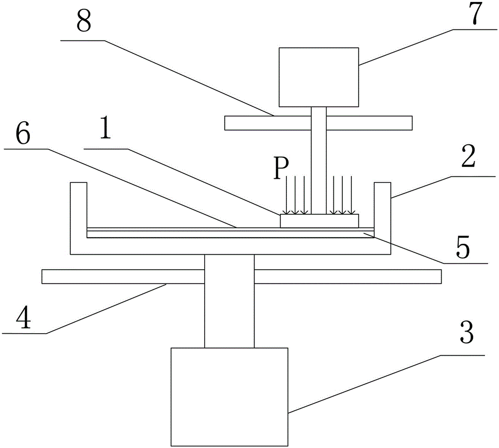
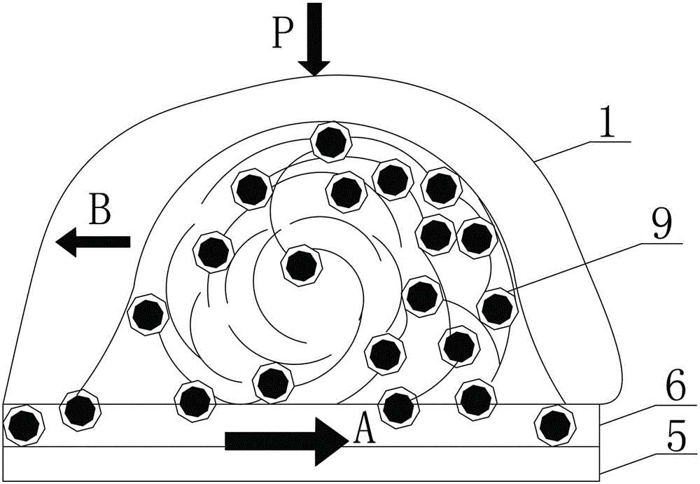
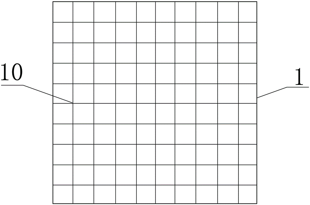
[0034] see Figure 1 to Figure 4 The first embodiment of the present invention provides a method for mechanically grinding micro-nano pores on a metal surface, comprising: providing a grinding and polishing liquid 6 containing abrasive particles 9 and a metal workpiece 1 with a plurality of defects 10 formed on the surface; Under the action of the grinding and polishing liquid 6, the surface of the metal workpiece 1 formed with a plurality of defects 10 is mechanically ground, so that the grinding and polishing liquid 6 entrains the abrasive particles 9 and continuously lands on the metal workpiece 1 Each defect 10 in each defect 10 performs vortex motion to grind the wall surface of the corresponding defect, and continuously washes away from each defect 10 on the metal workpiece 1, thereby forming micro-nano holes at each defect on the metal workpiece 1.

[0035] In this embodiment, the metal workpiece 1 is made of SUS304 stainless steel. The grinding and polishing liquid 6 ...

Embodiment 2

[0040] Embodiment two: basically the same as embodiment one, the difference is:

[0041] The method for forming micro-nano holes by mechanically grinding the metal surface provided in the second embodiment is different from the first embodiment in that the load P applied to the surface of the processed workpiece is different. When the load P=2.97Kg (0.023MPa), other conditions remained unchanged from Example 1, and obtained Figure 5 In the photomicrograph of the surface of the micropores, the diameter of the micropores is about 2-3 μm, and there are no nanopores, and the distribution density of the micropores is slightly smaller than that in Example 1. It shows that under heavy load, the surface removal polishing process is strengthened, so that the nano-holes disappear and only micro-holes are left. Pore ​​forming and surface removal polishing rates of the surface are a competing process, and under heavy loads, the surface removal rate is higher than the surface pore formin...

Embodiment 3

[0042] Embodiment three: basically the same as embodiment two, the difference is:

[0043] The method for forming micro-nano pores by mechanically grinding the metal surface provided in Example 3 is different from Example 2 in that the grinding time is prolonged. When the grinding time was extended to 40 minutes from 20 minutes, other conditions remained unchanged with embodiment two, obtained Image 6 In the photomicrograph of the surface of the micropores, the diameter of the micropores is about 2 μm, which is slightly smaller than that in Example 2, and there are no nano-holes, and the density of the micropores is also reduced. It is further confirmed that the surface removal rate is higher than the surface micropore formation rate.


PUM

PropertyMeasurementUnit
particle sizeaaaaaaaaaa
pore sizeaaaaaaaaaa
pore sizeaaaaaaaaaa

Abstract

The invention provides a forming method for metal surface micro-nano holes through mechanical lapping. The forming method comprises the steps that a lapping and polishing solution containing lapping particles and a metal workpiece with defects formed on the surface are provided; under the action of the lapping and polishing solution, mechanical lapping is carried out on the surface, with the defects, of the metal workpiece, the lapping and polishing solution is made to coerce the lapping particles to constantly carry out eddy lapping movement in the defects, lapping chips are generated by lapping the walls of the defects, the lapping particles and the lapping chips in the defects are flushed out constantly, and thus the micro-nano holes are formed in the defects. The invention further provides a lapping and polishing machine used in the forming method. Due to the fact that by means of the forming method, the micro-nano holes with the aperture capable of reaching the submicro dimension can be quickly formed in the defects, the forming time of the micro-nano holes is greatly shortened, the peripheries of the holes are in smooth transition, the phenomenon of stress concentration does not exist, the inner surfaces of the holes are regular and smooth, and the holes are hemispherical holes or cylindrical holes with the hemispherical bottoms.

Description

technical field [0001] The invention relates to a metal surface texturing treatment method and equipment, in particular to a forming method for mechanically grinding micro-nano holes on a metal surface and a grinding and polishing machine. Background technique [0002] The microporous texture on the metal surface can make the friction surface distribute micropores, which helps to improve the lubrication state of the friction pair, and the micropores store lubricant to prevent "dry grinding"; it can also increase the specific surface area of ​​the metal, which helps to improve the surface Adsorption and surface chemical or biological reaction effects. In the preparation of thin films, the microporous texture on the metal surface can improve the binding force of the film base, release the residual stress in the film, improve the load bearing capacity of the film, and prolong the service life of the film. For the connection of heterogeneous materials, such as metal and plastic...

Claims


Application Information

Patent Timeline
Patent Type & Authority Applications(China)
IPC IPC(8): B24B37/025
CPCB24B37/025
Inventor 郑锦华吴双廖晓燕魏新煦王俊杰
Owner ZHENGZHOU UNIV
Learn More