Comprehensive utilization system for sintering waste heat

A waste heat and waste heat boiler technology, applied in the field of metallurgical cooling equipment, can solve problems such as poor cooling effect, inconsistent cooling effect, and unadjustable air volume, and achieve good sealing, good cooling effect, and uniform recovery of waste heat.

Active Publication Date: 2015-11-18
宝鸡市晋旺达机械设备有限公司
View PDF10 Cites 10 Cited by
  • Summary
  • Abstract
  • Description
  • Claims
  • Application Information

AI Technical Summary

Problems solved by technology

For example, the Chinese invention patent application with the application number 201310419503.8 and the name of the invention as a vertical cooling kiln discloses a vertical cooling kiln. Air supply, in this way, because the air enters through the air duct and the hood, the wind resistance is large, and the air volume cannot be adjusted, so the air duct near the air inlet has a large air volume, while the air duct far away from the air inlet has a small air volume. Affects the heat replacement of sintered ore; similarly, the air outlet is on one side above the vertical kiln, and the single air outlet also forms a large local air volume and a small local air volume, resulting in differences in cooling effects at different positions
At the same time, the production and maintenance costs of the air duct and hood are high, the operating cost is high, the maintenance workload is heavy, and the kiln life is short, which is not conducive to the stable operation of the sintering machine
[0006] The patent number is 200910187381.8, and the invention name is the vertical tank type recovery device and utilization method of waste heat resources in the sintering process. The air intake also has the problem of large wind resistance and the inability to adjust the air volume, the partial air volume of the air outlet is different, and the cooling effect is inconsistent
Moreover, since there is no air volume adjustment device in the air inlet duct, the air intake volume cannot be adjusted, and the air outlet of the air duct discharges air from one side, which is easy to form a short circuit of the air flow, resulting

Method used


Image

  • Comprehensive utilization system for sintering waste heat
  • Comprehensive utilization system for sintering waste heat
  • Comprehensive utilization system for sintering waste heat

Examples


Embodiment Construction

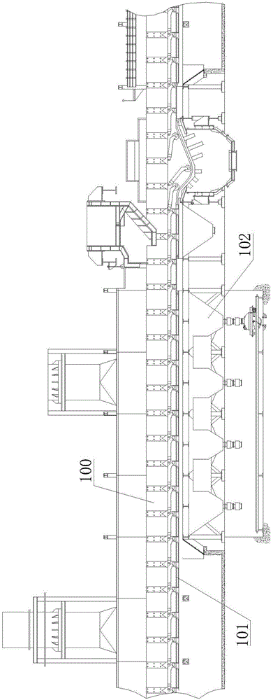
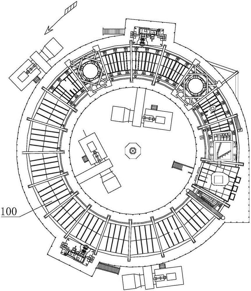
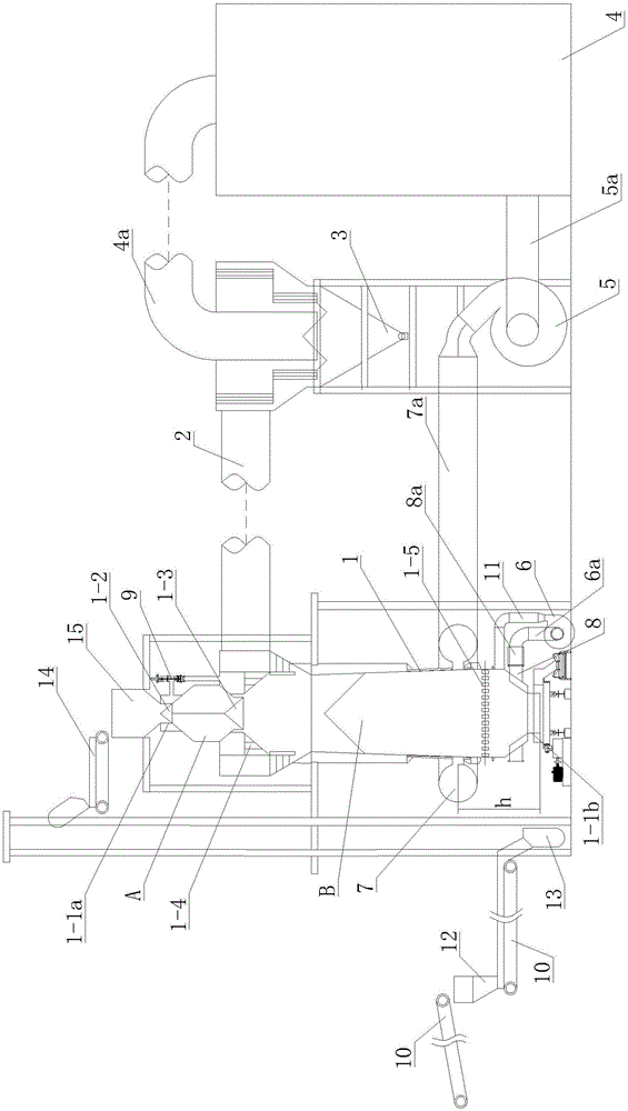
[0027] like image 3 , Figure 4 and Figure 5 As shown, the sintering waste heat comprehensive utilization system of this embodiment includes a cooling tower 1, a hot air delivery pipe 2, a fine powder separator 3, a waste heat boiler 4, an induced draft fan 5, a cooling blower 6, an air inlet surrounding pipe 7, and a cold air negative pressure pipe 8. Among them, the hot air delivery pipe 2 is connected to the cooling tower 1 and the fine powder separator 3, the fine powder separator 3 and the waste heat boiler 4 are connected through a pipe 4a, the induced draft fan 5 is connected to the waste heat boiler 4 through the induced air pipe 5a, and is passed through the air inlet The pressurizing pipe 7a is connected to the air inlet pipe 7, the cooling blower 6 is connected to the cold air negative pressure pipe 8 through the cold air inlet pipe 6a, and the cooling blower 6 is connected to the cold air pressure pipe 11 located below the air inlet pipe 7, and the cold air Th...


PUM


Abstract

A comprehensive utilization system for sintering waste heat comprises a cooling tower, a fine powder separator, a waste heat boiler, an induced draft fan, an air intake peripheral pipe and a cold air negative-pressure pipe. The air intake peripheral pipe is arranged on the periphery of the middle-lower part of the cooling tower, the air intake peripheral pipe is communicated with the interior of the cooling tower through air inlets arranged along the circumference at intervals, and the air intake peripheral pipe is connected with the induced draft fan through an air intake pressurization pipe. The cold air negative-pressure pipe is arranged above a discharging port of the cooling tower, the cold air negative-pressure pipe is connected with a cooling air blower through a cold air intake pipe, the cooling air blower is simultaneously connected with a cold air pressurization pipe located below the air intake peripheral pipe, and the cold air negative-pressure pipe and the cold air pressurization pipe are both communicated with the interior of the cooling tower. A material distribution area and a cooling area located below the material distribution area are formed in the cooling tower, a feeding port is formed in the top of the cooling tower, and the discharging port is formed in the bottom of the cooling tower. A material receiving seal valve is arranged in the cooling tower and located below the feeding port. A material distribution seal valve is arranged in the cooling tower and located above the opening of the material distribution area. According to the comprehensive utilization system for the sintering waste heat, secondary hot air generated in the cooling process can be recycled, energy consumption is reduced, and environmental pollution is completely eradicated.

Description

technical field [0001] The invention relates to metallurgical cooling equipment, in particular to a waste heat comprehensive utilization system matched with sintering equipment. Background technique [0002] The sintering system is a large-scale equipment that provides high-quality raw materials for the blast furnace. Among them, the cooling of the sintered finished ore is the biggest bottleneck affecting the sintering cost. In the case of weak steel market, energy saving, high efficiency and environmental protection are the primary considerations of every steel plant. Studies have shown that the waste heat of flue gas from the main flue of the sintering machine accounts for about 13% to 23% of the energy consumption of the sintering process, and the waste heat of the exhaust gas from the cooler accounts for 19% to 35% of the energy consumption of the sintering process, and the sum of the two is as high as 50%. The production of secondary energy is 1.62GJ / ton. It can be se...

Claims


Application Information

Patent Timeline
IPC IPC(8): F27D17/00
CPCY02P10/25
Inventor 关兴旺张国庆关珍旺关越
Owner 宝鸡市晋旺达机械设备有限公司
Why Eureka
Try Eureka