
Efficient acceleration control method for permanent-magnet synchronous motor

A permanent magnet synchronous motor, acceleration control technology, applied in the direction of motor generator control, electronic commutation motor control, control system, etc., can solve the problems of difficult implementation, poor anti-interference ability, complex algorithm structure of vector control technology, etc., to achieve The effect of shortening the acceleration time and speeding up the response speed

Inactive Publication Date: 2015-11-18
CHONGQING UNIV OF POSTS & TELECOMM
View PDF3 Cites 17 Cited by
  • Summary
  • Abstract
  • Description
  • Claims
  • Application Information

AI Technical Summary

Problems solved by technology

[0004] However, various existing motor control strategies still have various deficiencies. The algorithm structure of vector control technology is relatively complex, and it is necessary to decouple the AC and DC axis currents of the motor. It is difficult to implement and requires relatively high requirements for the controller. , and its response to speed is slow, and its anti-interference ability is poor; direct torque control technology has poor speed regulation performance at low speed; modern control theory and intelligent control research mostly stay at the theoretical stage

Method used


Image

  • Efficient acceleration control method for permanent-magnet synchronous motor
  • Efficient acceleration control method for permanent-magnet synchronous motor
  • Efficient acceleration control method for permanent-magnet synchronous motor

Examples


Embodiment Construction

[0025] The preferred embodiments of the present invention will be described in detail below with reference to the accompanying drawings.

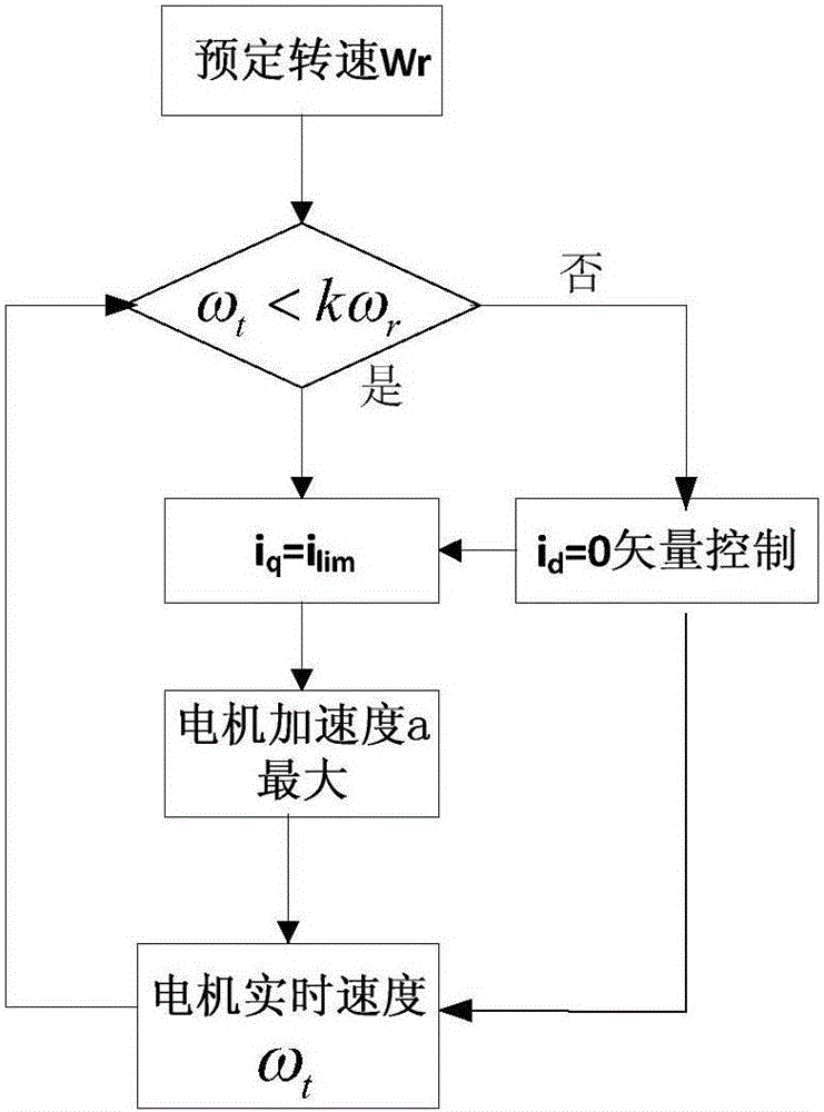
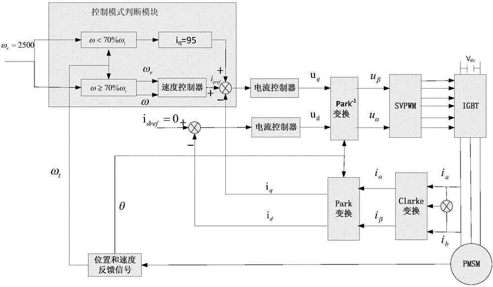
[0026] like figure 1 and figure 2 As shown, the flow chart and structural block diagram of the high-efficiency acceleration control method of the permanent magnet synchronous motor of the present invention, the specific steps of the method of the present invention are as follows:

[0027] First define the following parameter quantities:

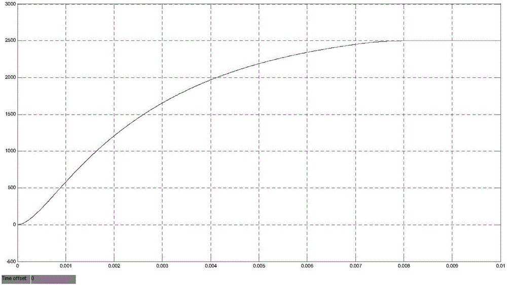
[0028] In this embodiment, the system parameter setting value is: target speed ω r =2500r / min, k=0.7, stator limit current i lim =95A.

[0029] Step (a): Detect the position information of the motor through the sensor, and then differentiate the position information with respect to time to obtain the actual speed ω of the motor t and return to the system;

[0030] Step (b): put ω t k times kω of the input speed of the system r For comparison, here kω r =1750r / min, determine the control mode of th...


PUM


Abstract

The invention relates to an efficient acceleration control method for a permanent-magnet synchronous motor. The efficient acceleration control method comprises the steps as follows: the rotating speed of the permanent-magnet synchronous motor is detected in real time and is compared with a target rotating speed; when the rotating speed of the motor is less than k (k is less than or equal to 1) times of the target rotating speed, the permanent-magnet synchronous motor enters an efficient acceleration control mode; the torque axis current iq reaches the maximum stator current value ilim under the limiting conditions of an inverter and the permanent-magnet synchronous motor to obtain the maximum electromagnetic torque, so that the motor always approaches the target rotating speed at the maximum acceleration; the steps are an open-loop control stage; when the rotating speed of the motor reaches k times or more of the target rotating speed, the permanent-magnet synchronous motor quits the efficient acceleration control mode, enters a stable control mode, and is switched into a vector control strategy of id=0; and the permanent-magnet synchronous motor enters double closed-loop control of the current and the rotating speed, so that the motor relatively stably approaches the target rotating speed; and the system stably runs at the expected rotating speed. According to the method, when the permanent-magnet synchronous motor is started or the preset rotating speed greatly changes, the target rotating speed can be reached as soon as possible; the acceleration time of the motor is greatly shortened; and the efficient acceleration control method is simple in structure and easy to realize.

Description

technical field [0001] The invention belongs to the technical field of motor control, and relates to a high-efficiency acceleration control method for a permanent magnet synchronous motor. Background technique [0002] With the emergence of new power electronic devices GTO, IGBT, etc., the synchronous motor speed control system has developed to a new stage. The permanent magnet synchronous motor speed control system has good static and dynamic characteristics and is suitable for use in machine tools, robots and flexible manufacturing systems. middle. The rotor of the motor is excited by permanent magnets, which eliminates the loss of rotor excitation. Nowadays, permanent magnet synchronous motors are widely used because of their advantages such as convenient maintenance, strong controllability, low environmental impact, high motor efficiency, and high power factor. Permanent magnet synchronous motors are developing towards high power, high speed, high efficiency and miniat...

Claims


Application Information

Patent Timeline
Patent Type & Authority Applications(China)
IPC IPC(8): H02P21/00
Inventor 黄智宇乔旭日夏天骏孙昌波
Owner CHONGQING UNIV OF POSTS & TELECOMM
Learn More