Device for treating and recycling aluminum electrolysis solid waste

A technology for solid waste and aluminum recycling, applied in the field of metallurgical environment, can solve the problems of affecting cement, separation, secondary pollution, etc.

Inactive Publication Date: 2015-11-25
SHENYANG BEIYE METALLURGIGAL TECH CO LTD
View PDF4 Cites 16 Cited by
  • Summary
  • Abstract
  • Description
  • Claims
  • Application Information

AI Technical Summary

Problems solved by technology

[0005] 3. Anode carbon residue
As early as the 1950s, people began to study how to deal with and recycle the waste cathode carbon blocks and carbon slag produced by aluminum electrolytic cells. There are no more than three methods: 1. As an additive in other chemical production processes, such as The waste cathode carbon block is ground into powder as an additive in cement production, but this part is used in a small amount, because the fluoride in the waste cathode carbon block will affect the quality of cement because it is used too much, so it is not welcomed by cement manufacturers ; 2 is used as fuel, but there is also a secondary pollution problem as a fuel; 3 is to recycle the electrolyte, which is the most studied method of using flotation to combine the carbon and electrolyte in the anode carbon slag and the spent cathode carbon block However, until now, this method has not been successfully applied in industry, because the electrolyte cannot be completely separated from the spent cathode carbon block by flotation, and the waste water generated by the flotation process is also likely to cause secondary Pollution
In 1958, the US2858198 patent proposed a method of separating the electrolyte components in the spent cathode carbon block of aluminum electrolytic cells by distillation, but the device used in this method was a tower structure, and the heating method was external heating, probably due to Due to complex devices, difficult operation, and high energy consumption, it has not been applied in industry until now.

Method used


Image

  • Device for treating and recycling aluminum electrolysis solid waste
  • Device for treating and recycling aluminum electrolysis solid waste
  • Device for treating and recycling aluminum electrolysis solid waste

Examples


Embodiment 1

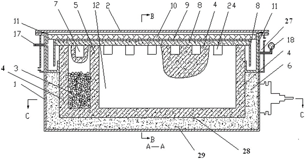
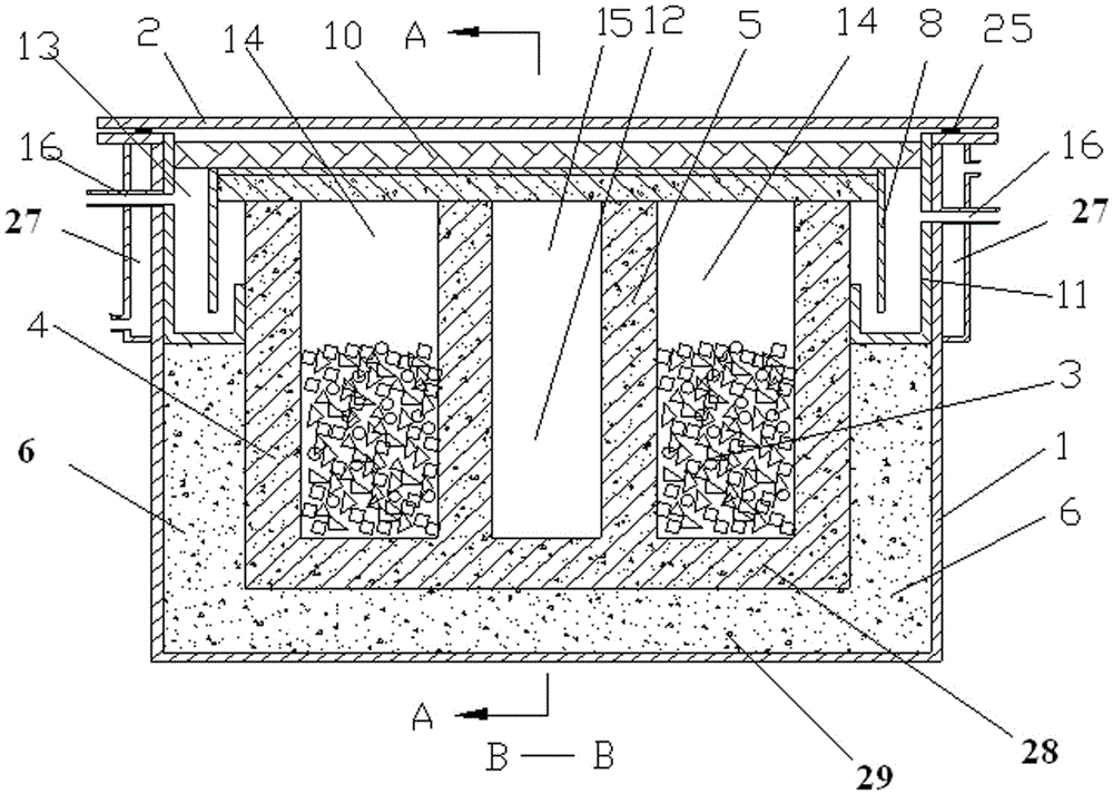
[0052] The structure of the device for processing and recycling solid waste from aluminum electrolytic cells is as follows: figure 1 , figure 2 and image 3 Shown; resistance heating element is П-type design;

[0053] Including furnace shell 1, furnace cover 2, furnace lining, furnace wall refractory wall 4, resistance heating element 3, refractory wall 5 in the middle of the furnace, alkali metal crystallizer 11, heat insulation cover plate 8, metal cover 9. Electrode, auxiliary material chamber 12, electrolyte crystallization chamber and alkali metal crystallization chamber 13;

[0054] The furnace shell 1 is a box-type metal shell made of steel metal material; the outer edge of the top of the furnace shell 1 has a flange structure, and the outer wall of a section of the furnace shell 1 under the flange structure is provided with a cooling water jacket 27, The furnace shell 1 at the lower part of the flange structure is welded with a vacuum exhaust pipe 16; the lower edg...

Embodiment 2

[0077] Figure 4 C-C sectional view of the U-shaped resistance heating element and electrode structure when the resistance heating element of the present invention is a U-shaped design;

[0078] The difference between device structure and embodiment 1 is:

[0079] (1) The resistance heating element is a U-shaped structure design;

[0080] (2) The resistance heating element is 10cm higher than the graphite conductor;

[0081] The difference between method and embodiment 1 is:

[0082] (1) The briquetting material is made by mixing and pressing the grinding powder of the waste refractory lining of the electrolytic cell and aluminum ash; the Na in the grinding powder of the waste refractory lining of the electrolytic cell 2 The O component is 5%, the electrolyte component is 10%; the elemental aluminum in the aluminum ash is 15%, and the ingredients are based on the added aluminum ash. The aluminum in the aluminum ash can reduce the Na in the waste refractory lining. 2 O is c...

Embodiment 3

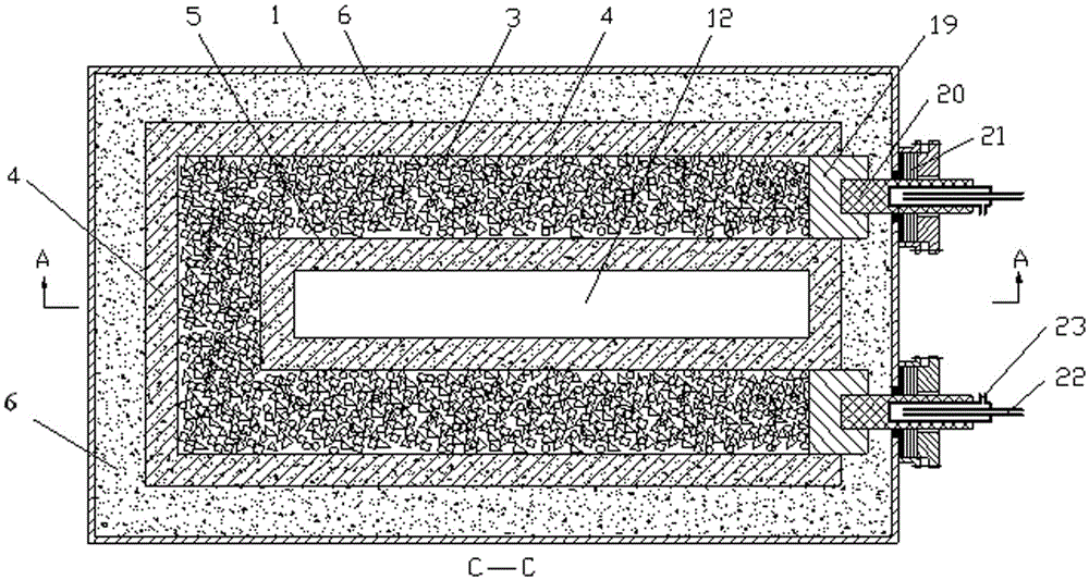
[0087] Figure 5 It is a C-C sectional view when the resistance heating element of the present embodiment is designed as two independent and parallel linear shapes;

[0088] The difference with embodiment 2 is:

[0089] (1) The resistance heating element is designed as two independent and parallel linear structures. The two electrodes of each independent resistance heating element are respectively located on the two sides of the electric furnace; at this time, the two electrodes on the same side are connected to the power supply Power connection, the two electrodes on the other side are connected with metal conductors;

[0090] (2) The resistance heating element is 20cm higher than the graphite conductor;

[0091] The difference between method and embodiment 2 is:

[0092] (1) The briquetting material is made by mixing and pressing the grinding powder of the waste refractory lining of the electrolytic cell and Al-Fe alloy powder. The aluminum content in the Al-Fe alloy is 6...


PUM

PropertyMeasurementUnit
particle diameteraaaaaaaaaa
particle sizeaaaaaaaaaa

Abstract

A device for treating and recycling aluminum electrolysis solid waste comprises a furnace shell, a furnace cover, a furnace lining, a fire wall fireproof material wall, a furnace bottom fireproof material lining, a resistance heating body, a fireproof material wall in the middle in a furnace, an alkali metal crystallizer, a heat isolation cover plate, a metal cover, electrodes, an auxiliary material chamber, an electrolyte crystallization chamber and an alkali metal crystallization chamber. The resistance heating body is composed of waste cathode carbon block fragments with the particle diameter smaller than 10 cm. According to the device, carbon, alkali metal and electrolytes in waste cathode carbon blocks and a carbon lining can be thoroughly separated, and the device is an energy-saving and environment-friendly aluminum electrolysis solid waste treating device and is very suitable for being applied and popularized in industry on a large scale.

Description

technical field [0001] The invention belongs to the technical field of metallurgy and environment, and in particular relates to a device for processing and recycling aluminum electrolysis solid waste. Background technique [0002] Aluminum in the industry is produced by electrolysis using a cryolite-alumina electrolyte system at a temperature of 950~980°C. During the aluminum electrolysis production process, the following four types of solid waste are produced: [0003] 1. Waste cathode carbon block. The waste cathode carbon block of aluminum electrolytic cell refers to the cathode carbon block and side carbon block taken out from the damaged electrolytic cell after a period of electrolysis of the aluminum electrolytic cell after the bottom of the cell is damaged, including the side carbon block The carbon block formed by tamping paste between the block and the bottom cathode carbon block, and the carbon block formed by the tamping paste between the cathode carbon blocks at...

Claims


Application Information

Patent Timeline
Patent Type & Authority Applications(China)
IPC IPC(8): C25C3/06
Inventor 冯乃祥
Owner SHENYANG BEIYE METALLURGIGAL TECH CO LTD
Why Eureka
Try Eureka