Bias voltage regulation and control aperture plate plasma immersion ionic deposition DLC method

An ion deposition and plasma technology, which is applied in gaseous chemical plating, metal material coating process, coating, etc., can solve the problems of poor bonding force, difficult adjustment of film properties, uneven deposition of DLC film, etc. The effect of improved binding force, stable glow discharge and easy industrial production

Active Publication Date: 2015-12-02
HARBIN INST OF TECH
View PDF3 Cites 6 Cited by
  • Summary
  • Abstract
  • Description
  • Claims
  • Application Information

AI Technical Summary

Problems solved by technology

[0007] The present invention aims to solve the problems of poor binding force, difficult regulation of film properties and non-uniformity of DLC film deposited o

Method used


Image

  • Bias voltage regulation and control aperture plate plasma immersion ionic deposition DLC method
  • Bias voltage regulation and control aperture plate plasma immersion ionic deposition DLC method
  • Bias voltage regulation and control aperture plate plasma immersion ionic deposition DLC method

Examples


specific Embodiment approach 1

[0029] Specific implementation mode 1: In this implementation mode, the bias control grid plasma immersion ion deposition DLC method is carried out according to the following steps:

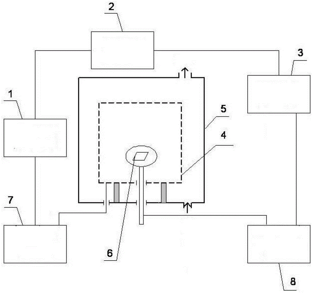
[0030] 1. Place the grid 4 in the vacuum chamber 5, and then place the workpiece on the sample holder 6 in the grid 4. The grid 4 is insulated from the workpiece, and the grid 4 passes the high-voltage pulse of the wire and the grid high-voltage pulse power supply 1. The output end is connected, and a grid high-voltage pulse waveform oscilloscope 7 is arranged between the grid 4 and the grid high-voltage pulse power supply 1; the workpiece is connected to the pulse output end of the workpiece high-voltage pulse power supply 3 through a wire, and the workpiece and the workpiece high-voltage pulse A workpiece high-voltage pulse waveform oscilloscope 8 is arranged between the power sources 3; the phase between the workpiece high-voltage pulse and the grid high-voltage pulse is controlled by the pulse...

specific Embodiment approach 2

[0039] Embodiment 2: This embodiment differs from Embodiment 1 in that: in step 2, the pulse voltage of the grid high-voltage pulse outputted by the grid high-voltage pulse power supply 1 is adjusted to 2kV, the frequency is 2000Hz, and the pulse width is 20μs. Others are the same as the first embodiment.

specific Embodiment approach 3

[0040] Embodiment 3: The difference between this embodiment and Embodiment 1 or 2 is that in step 2, the pulse voltage of the workpiece high-voltage pulse output by the workpiece high-voltage pulse power supply 3 is adjusted to 3kV, the frequency is 2000Hz, and the pulse width is 20μs. Others are the same as those in Embodiment 1 or 2.


PUM

PropertyMeasurementUnit
Pulse widthaaaaaaaaaa
Thicknessaaaaaaaaaa
Nanohardnessaaaaaaaaaa

Abstract

The invention discloses a bias voltage regulation and control aperture plate plasma immersion ionic deposition DLC method, and relates to a plasma immersion ionic deposition DLC method. The method aims at solving the problems that when an existing MPIID method is used for depositing a DLC film, the bonding force is poor, the performance of the film is not prone to being regulated and controlled, and the DLC film deposited on large or complex parts is uneven. The method includes the steps that (1) an aperture plate and a workpiece are arranged in a vacuum chamber, the workpiece is placed on a sample support in the aperture plate, the aperture plate and the workpiece are insulated, the aperture plate is connected with a aperture plate high-voltage pulse power source, and the workpiece is connected with a workpiece high-voltage pulse power source; (2) workpiece sputter cleaning is carried out; (3) plasma nitrogen treatment is carried out; (4) sputtering etching treatment is carried out; (5) a SiC transition layer is manufactured; and (6) a bias voltage regulation and control thin film is manufactured. The method is used for manufacturing the bias voltage regulation and control aperture plate plasma immersion ionic deposition DLC film.

Description

technical field [0001] The invention relates to a plasma immersion ion deposition DLC method. Background technique [0002] DLC (DiamondLikeCarbon) film has many excellent properties, such as low friction coefficient, high hardness and wear resistance, chemical inertness, optical transparency in the infrared spectrum range, low electrical conductivity and biocompatibility, which make DLC film have a wide range of applications. Application prospect. [0003] DLC films can be prepared by physical vapor deposition (PVD) methods (such as sputtering or arc evaporation) and plasma enhanced chemical vapor deposition (PECVD-PlasmaEnhancedChemicalVaporDeposition). PECVD technology is to connect a negative bias power supply to the workpiece, and use the glow discharge of hydrocarbon gas (such as acetylene or methane) to deposit DLC film. The laboratory generally uses radio frequency (rf-13.56MHz) power supply. The preparation of DLC by rf-PECVD is not easy for large-scale industrial...

Claims


Application Information

Patent Timeline
IPC IPC(8): C23C16/27C23C16/02C23C16/44
Inventor 田修波吴明忠巩春志
Owner HARBIN INST OF TECH
Why Eureka
Try Eureka