System and method of fast pyrolysis of oil shale

An oil shale, fast technology, applied in the chemical industry, can solve the problems of short continuous start-up time of the system, complex equipment structure, high maintenance cost, etc., to improve the efficiency of rapid pyrolysis, simplify the process flow, and increase the yield of shale oil Effect

Active Publication Date: 2015-12-09
SHENWU TECH GRP CO LTD
View PDF8 Cites 10 Cited by
  • Summary
  • Abstract
  • Description
  • Claims
  • Application Information

AI Technical Summary

Problems solved by technology

At present, the technologies developed based on the direct heat transfer furnace mainly include the ATP furnace (solid heat carrier) in Australia, the Galoter furnace (solid heat carrier) in Estonia, and the Tosco-II oil shale dry distillation technology developed by Tosco Corporation of the United States ( Solid heat carrier), the oil shale pyrolysis system researched in China in the past two years mainly includes the DG technology (solid heat carrier) of Dalian University of Technology and the oil shale fluidized bed dry distillation and decarburization process developed by Shanghai Bosheng Company ( Gas heat carrier), but the direct heating technology of heat carrier involves the separation and reheating of heat carrier, etc., and the process is complicated, which leads to the short continuous start-up time of the system
The indirect heat transfer furnace mainly includes rotary kiln, walking furnace and rotary furnace, etc., but there are mechanical movements, complex equipment structure, high maintenance cost, and indirect heat transfer generally has low thermal efficiency.

Method used


Image

  • System and method of fast pyrolysis of oil shale
  • System and method of fast pyrolysis of oil shale
  • System and method of fast pyrolysis of oil shale

Examples


Embodiment 1

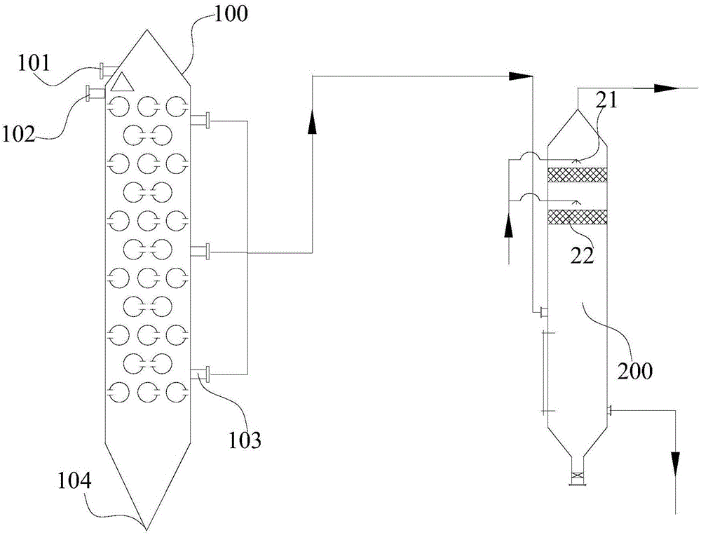
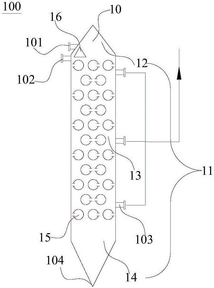
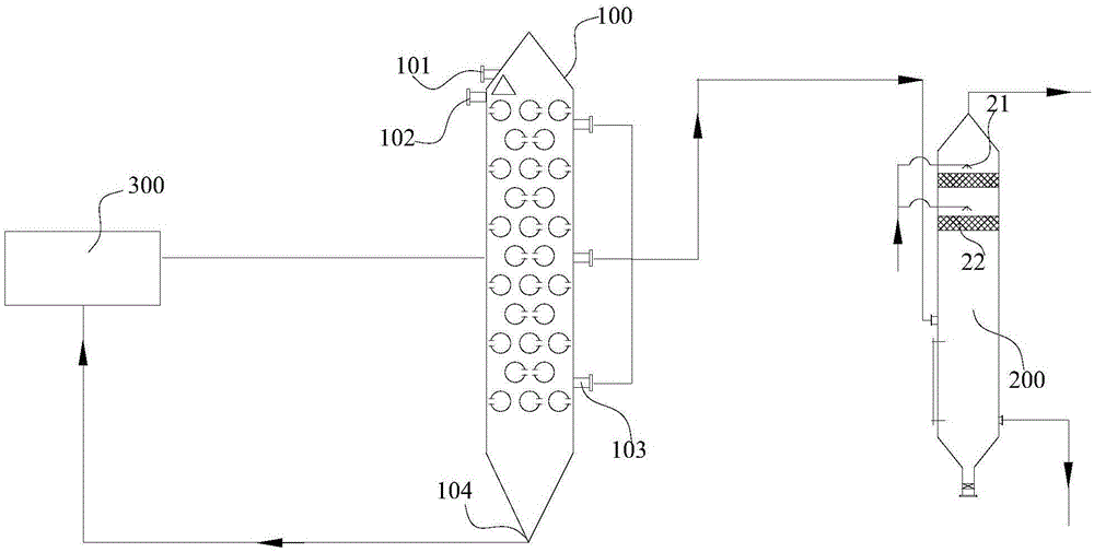
[0155] This embodiment 1 adopts Figure 1-6 The system for rapid pyrolysis of biomass, in which 30 layers of regenerative radiant tubes 15 are distributed in the pyrolysis zone 13 along the height of the reactor body 10 at intervals, and adjacent regenerative radiant tubes are horizontally and the reactor body The two directions of height are spaced at the same distance and distributed in parallel. The regenerative radiant tube adopts a circular tube with a diameter of 100mm. The distance between the outer walls of adjacent radiant tubes is 100mm horizontally, and the distance between the outer walls of adjacent radiant tubes on the upper and lower layers is 100mm.

[0156] The oil shale rapid pyrolysis reaction system of the present invention is used to process the oil shale with a particle size in the range of 3mm or less. The oil shale analysis data, process operation parameters and material balance are shown in Table 1-3. The rapid pyrolysis time 30s.

[0157] Table 1 Oil shal...

Embodiment 2

[0165] This embodiment 2 adopts Figure 1-2 The oil shale rapid pyrolysis system in which the 6-layer regenerative radiant tubes 15 are distributed in the pyrolysis zone 13 along the height of the reactor body 10, and the adjacent regenerative radiant tubes are arranged horizontally and the reactor The height of the main body is spaced at the same distance in two directions and distributed in parallel and staggered. The regenerative radiant tube adopts a circular tube with a diameter of 500mm. The distance between the outer walls of adjacent radiant tubes is 500mm horizontally, and the distance between the outer walls of adjacent radiant tubes on the upper and lower layers is 500mm.

[0166] The oil shale rapid pyrolysis reaction system of the present invention is used to process the oil shale with a particle size in the range of 2mm or less. The raw material of the oil shale to be pyrolyzed is the same as in Example 1. The process operating parameters and material balance are sh...


PUM

PropertyMeasurementUnit
heightaaaaaaaaaa
diameteraaaaaaaaaa
particle diameteraaaaaaaaaa

Abstract

The invention discloses a system and a method of fast pyrolysis of oil shale. The system comprises a fast pyrolysis reactor and a spray tower, wherein the fast pyrolysis reactor comprises a reactor body, a multilayer regenerative radiant tube, an oil shale inlet, a distributing device, a distributing gas inlet, a plurality of pyrolysis gas outlets and a carbocoal outlet, the fast pyrolysis reactor is suitable for performing fast pyrolysis treatment on the oil shale by adopting the regenerative radiant tube, so as to obtain carbocoal and pyrolysis gas, and the spray tower is connected with the plurality of pyrolysis gas outlets and is suitable for performing spray treatment on the pyrolysis gas by adopting cooling liquid, so as to obtain shale oil and gas. According to the system, fast pyrolysis of the oil shale can be realized, and the yield of the obtained shale oil is high.

Description

Technical field [0001] The present invention belongs to the field of chemical engineering. Specifically, the present invention relates to a system and method for rapid pyrolysis of oil shale. Background technique [0002] The oil shale pyrolysis system can be divided into direct heat transfer furnace and indirect heat transfer furnace according to the heating method, and the direct heat transfer furnace can be divided into solid heat carrier and gas heat carrier pyrolysis furnace according to the different heat carriers. Since direct heat transfer is faster and more efficient than indirect heat transfer, modern dry distillation technology mainly uses direct heat transfer furnaces. At present, the technologies developed based on direct heat transfer furnaces mainly include ATP furnace (solid heat carrier) in Australia, Galoter furnace (solid heat carrier) in Estonia and Tosco-Ⅱ oil shale dry distillation technology developed by Tosco in the United States ( Solid heat carrier), th...

Claims


Application Information

Patent Timeline
Patent Type & Authority Applications(China)
IPC IPC(8): C10B53/06C10B47/00C10B27/00C10J3/60
Inventor 吴道洪陈水渺肖磊
Owner SHENWU TECH GRP CO LTD
Why Eureka
Try Eureka