Oxygen-consuming electrode and method for its production

A depolarization and electrode technology, applied in the direction of electrodes, battery electrodes, alkaline battery electrodes, etc., to achieve the effect of low ohmic voltage drop and small thickness

Inactive Publication Date: 2015-12-09
BAYER MATERIALSCIENCE AG
View PDF2 Cites 3 Cited by
  • Summary
  • Abstract
  • Description
  • Claims
  • Application Information

AI Technical Summary

Problems solved by technology

This results in relatively catalytically inactive coarse catalyst particles

Method used


Image

  • Oxygen-consuming electrode and method for its production
  • Oxygen-consuming electrode and method for its production
  • Oxygen-consuming electrode and method for its production

Examples


Embodiment 1

[0080] The starting material is nickel catenary (mesh size 500 μm, wire thickness 150 μm; thickness after rolling 120 μm) and 4 layers 70 μm thick and porosity 85% to 90% as current collector 1 which has been flattened 10 of three-dimensional expanded PTFE membranes.

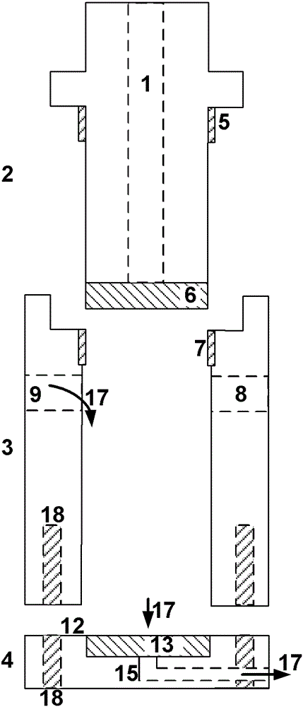
[0081] First, the nickel mesh 1 was activated in 25% by weight sulfuric acid for 1 minute, and then washed away with water. Subsequently, the nickel mesh was clamped in the figure 1 Between the base 4 and the housing 3 of the manufacturing unit (2, 3, 4) shown in, there is a 10cm 2 ?? (36 mm in diameter) geometric electrode area in a sheet free of frit 13 and sealed in the process by flat silicone seals (not shown) each in The mesh has a thickness of 1 mm above and below. Introduce silver cyanide solution (36g / lAgCN, 60g / lKCN, 45g / lKCN 2 CO 3 ) until the silver anode 6 is immersed in said solution at the anode support 2. Close entrances and exits. The cathode contacts are formed with the mesh 1 by four ti...

Embodiment 2

[0089] Electrodes were prepared analogously to Example 1. However, from silver nitrate solutions with different compositions (0.1MAgNO 3 , 0.06MH 3 PO 4 ) and generate catalytically active silver structures by different configurations of current versus time. Deposition was achieved by 25 consecutive cycles of this protocol: 5 current pulses with a length of 60 ms and a waiting time between pulses of 1 s by applying a voltage of 60 V (producing a current of approximately 25 A), followed in each case by Deposition at 10A for 1s.

[0090] When the above current density is 4.0kA / m 2 The electrode attained a potential of -200 mV vs. NHE when operated as an oxygen depolarized cathode in a half-cell under conditions of . Silver content is about 350g / m 2 electrode area.

Embodiment 3

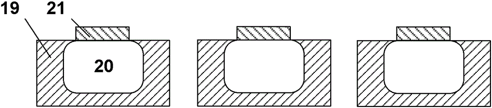
[0092] The catenary used for electrode manufacture was a titanium mesh 20 (mesh size 500 μm, wire thickness 150 μm) that had been flattened. The latter was masked on one side by an adhesive film and coated with a 2-pack solder resist 19 (PetersSD2444NB-M). The film was peeled off and excess resist was removed from the web using compressed air. After curing, remove resist residues on uncoated surfaces again with fine sandpaper (see image 3 ). The mesh was clamped in the fabrication unit as described in Example 1 for the silver-coated mesh (ie, no porous PTFE membrane). On a clean surface, a silver mesh 21 with a thickness of about 40 μm is made of silver cyanide solution (105g / lAgCN, 113g / lKCN, 60g / lK 2 CO 3 , 30g / lKOH) deposited at 0.5A for 300s. At the end of electrode fabrication, it is used in oxygen depolarized cathodes as a catenary that can be peeled from the titanium mesh since it does not adhere strongly to it. However, at the beginning it remained on the titani...


PUM

PropertyMeasurementUnit
diameteraaaaaaaaaa
diameteraaaaaaaaaa
lengthaaaaaaaaaa

Abstract

An oxygen-consuming electrode is provided, in particular for use in the chlor-alkali electrolysis, a new type of catalyst described coating as well as an electrolysis apparatus. It is a manufacturing process for the oxygen-consuming electrode, and their use in the chlor-alkali electrolysis or fuel cell technology will be further described. At least the oxygen-consuming electrode comprises a current collector and a gas diffusion layer with a catalytically active component, wherein the gas diffusion layer as at least one porous sheet is formed of a fluorinated polymer, in the introduced fine crystalline metallic catalyst particles as catalytically active component and electrically conductively connected via a first intermediate metallic layer with the current collector.

Description

technical field [0001] The present invention relates to oxygen depolarization electrodes, more particularly to oxygen depolarization electrodes for use in chlor-alkali electrolysis, which comprise novel catalyst coatings based on needle crystals of catalyst metals, and to electrolysis devices . The invention also relates to the production method of said oxygen depolarization electrode and the use of said oxygen depolarization electrode in chlor-alkali electrolysis or fuel cell technology. Background technique [0002] The invention proceeds from oxygen depolarization electrodes known per se, which take the form of gas diffusion electrodes and generally comprise an electrically conductive support and a gas diffusion layer comprising catalytically active components. [0003] Oxygen depolarization electrodes are in the form of gas diffusion electrodes. A gas diffusion electrode is one in which the three states of matter - solid, liquid, and gas - are in contact with each othe...

Claims


Application Information

Patent Timeline
Patent Type & Authority Applications(China)
IPC IPC(8): C25B11/03C25B11/04C25B11/08C25B1/34H01M4/24H01M4/86
CPCC25B1/46C25B11/035C25D5/08C25D5/18H01M4/8803H01M4/8817H01M4/8853C25D3/46C25D7/00Y02E60/50C25B11/031C25D5/617
Inventor A.布兰H.赫克罗特J.耶里森P.弗拉尼亚A.海尔M.施泰尔特
Owner BAYER MATERIALSCIENCE AG
Why Eureka
Try Eureka