Efficient optical glass melting tank

A high-efficiency optics and melting pool technology, applied in glass production, glass furnace equipment, glass manufacturing equipment, etc., can solve problems such as poor stripes, product bubbles, shorten the service life of the furnace, etc., to prevent bubbles and uniformity, and improve efficiency Effect

Active Publication Date: 2015-12-16
HUBEI NEW HUAGUANG NEW INFORMATION MATERIALS CO LTD
View PDF3 Cites 3 Cited by
  • Summary
  • Abstract
  • Description
  • Claims
  • Application Information

AI Technical Summary

Problems solved by technology

Usually, only the molten glass near the mouth of the nozzle can be output through the connecting pipe in time, so that most of the molten glass that has been melted is trapped in the bottom of the melting pool 2, resulting in low working efficiency of the melting pool, such as figure 1 As shown, the melting pool 2 is equipped with a batch material feeding port 1, a melting pool connecting pipe 8, a melting electrode, a melting pool liquid level line 12 and a gas burner heating system
If the flow rate of the connecting pipe 8 of the melting pool is increased, the incompletely melted molten glass in the upper layer of the melting pool 2 will be output, resulting in poor quality products such as bubbles and streaks
In addition, the residence time of molten glass in the melting pool 2 is too long, and the optical properties such as coloring degree and uniformity of the product may deteriorate.
[0004] Secondly, the molten glass in the melting tank is always in a flowing state, so it cannot be guaranteed that the molten glass entering the clarification tank through the connecting pipe is fully melted. If this happens, it will cause abnormal quality of the product such as bubbles and streaks.
When encountering similar problems, the solution is to increase the melting temperature or reduce the output. For example, increasing the melting temperature will not only aggravate the aging of the equipment and shorten the service life of the furnace, but also lead to the deterioration of the coloring degree of the product, and even the erosion of the refractory material into the molten glass. The occurrence of problems such as poor stripes, while reducing the output volume also reduces the working efficiency of the melting pool

Method used


Image

  • Efficient optical glass melting tank
  • Efficient optical glass melting tank
  • Efficient optical glass melting tank

Examples


Embodiment Construction

[0027] Below in conjunction with example the present invention will be further described.

[0028] Below in conjunction with example the present invention will be further described.

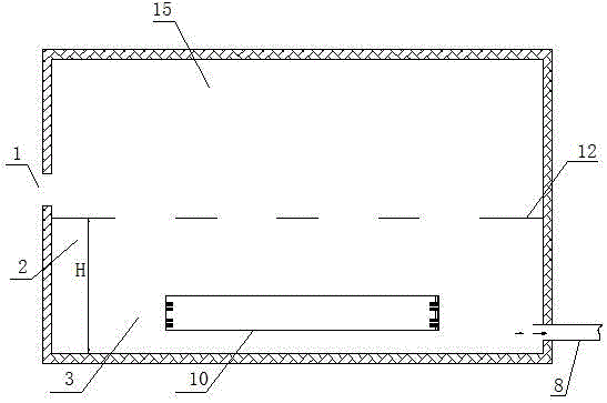
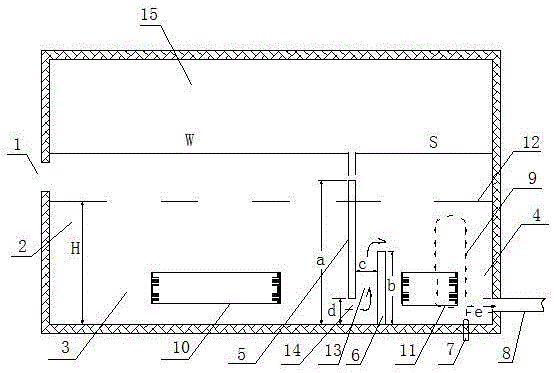
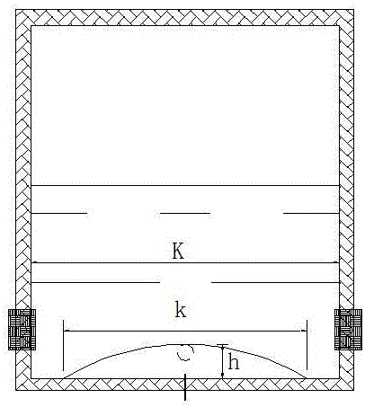
[0029] like Figure 2 to Figure 4 shown. This example provides a high-efficiency melting pool for melting environmentally friendly BaK and environmentally friendly F optical glass furnaces. The two ends of the melting pool 2 are respectively equipped with a batch material feeding port 1 and a melting pool connecting pipe 8. A gas burner heating system is installed above the melting pool 2. The depth H of the molten glass is 1000 mm, the width K of the melting pool is 1000 mm, and the melting pool is connected. The height h of the highest point of the pipe is 160mm, which is the same as that of the existing melting pool. The difference is that the melting pool 2 is provided with a separator 5 , a fluxing electrode 10 in the melting zone, a kiln ridge 6 , a fluxing electrode 11 in the feeding zo...


PUM

PropertyMeasurementUnit
heightaaaaaaaaaa
depthaaaaaaaaaa
widthaaaaaaaaaa

Abstract

The invention relates to an efficient optical glass melting tank, belongs to the technical field of optical glass melting, and mainly solves the problem of low work efficiency of a conventional melting tank. The efficient optical glass melting tank is mainly characterized by comprising a melting tank; a batch feeding opening and a melting tank communicating pipe respectively arranged at the two ends of the melting tank; a melting electrode arranged in the melting tank; a fuel gas burning gun heating system arranged above the melting tank; a partition of which the lower end is passage port-shaped is arranged in the melting tank, and used for diving the melting tank into a melting area and a feeding area; the melting electrode is a melting area melting acceleration electrode, and positioned in the melting area; a furnace ridge, a feeding area melting acceleration electrode and a feeding area bubbler are sequentially between the partition and the melting tank communicating pipe to form a passage to allow glass metal below the partition to flow above the furnace ridge and then flow to the melting tank communicating pipe. The discharging amount of the optical glass melting tank can be improved by 0.4-0.8 time on the premise that a melting area and the energy consumption are the same as those in the prior art, and the optical glass melting tank is mainly used for a furnace for continuous smelting production of high-quality optical glass.

Description

technical field [0001] The invention belongs to the technical field of optical glass melting, and in particular relates to a high-efficiency melting pool of a glass furnace, which is mainly used for the continuous melting production of high-quality optical glass. Background technique [0002] At present, the commonly used melting pools for the domestic production of crown and flint-type environmental or non-environmental-friendly optical glasses are generally divided into all-electric melting pools, full-flame melting pools and flame-electric hybrid melting pools according to heating methods. The all-electric melting pool furnace has less environmental pollution, relatively simple structure, and low cost, but the process debugging is complicated and the quality stability is poor. At present, it can only produce some crown or flint glass. The full-flame melting pool kiln has simple structure, less auxiliary equipment, and low cost, but the heating of the molten glass is mainl...

Claims


Application Information

Patent Timeline
Patent Type & Authority Applications(China)
IPC IPC(8): C03B5/182C03B5/18C03B5/235
CPCY02P40/57
Inventor 胡弦张欣瑞王拓徐华锋杨谧玲
Owner HUBEI NEW HUAGUANG NEW INFORMATION MATERIALS CO LTD
Why Eureka
Try Eureka