
High-efficiency heat exchangers for non-self-preheating gas burner radiant tubes

A gas burner, radiant tube technology, applied in the direction of heat exchanger type, indirect heat exchanger, heat exchange equipment, etc., can solve the problem of limited increase in heat exchange wall area, prolonging flue gas stroke and heat exchange time, heat exchange It can solve the problems of high temperature corrosion of the device, so as to achieve the effect of expanding the effective heat exchange wall area, prolonging the flow of flue gas, and improving the surface heat transfer coefficient.

Inactive Publication Date: 2017-07-21
武汉钢铁有限公司
View PDF3 Cites 0 Cited by
  • Summary
  • Abstract
  • Description
  • Claims
  • Application Information

AI Technical Summary

Problems solved by technology

It is not difficult to see that this patented technology increases the heat exchange wall area of ​​the heat exchanger, and at the same time makes full use of the flue gas entrainment mixing heating technology, but the structure is complex, the preparation technology is difficult, the return section is small in volume, and the heat exchange wall area is increased. The range is limited. At the same time, due to the complex structure, the limited space of the exhaust section of the radiant tube has not been fully utilized, and there have been no reports of actual production and application.
[0009] Based on the above, it can be seen that a lot of research has been carried out on the high efficiency of radiant tube heat exchangers at home and abroad, and various patented technologies have been formed. However, most of the patented technologies are mainly improvements on the basis of the original technology, mainly air and heat exchangers. The expansion of fins on the flue gas heat exchange wall, baffles to extend the flue gas stroke and heat exchange time, and flue gas entrainment and mixing, etc., have not substantially improved the area of ​​the heat exchange wall, and are common in actual production. High exhaust gas temperature, low heat exchange efficiency, high-temperature corrosion of the heat exchanger, etc.; although the patent disclosed by Fives Stein can increase the area of ​​the heat exchange wall, the structure is complex, the utilization rate of the limited space in the radiant tube is low, and the heat exchange The increase in the heat exchange wall area of ​​the device is limited, and there is no actual production application

Method used


Image

  • High-efficiency heat exchangers for non-self-preheating gas burner radiant tubes
  • High-efficiency heat exchangers for non-self-preheating gas burner radiant tubes
  • High-efficiency heat exchangers for non-self-preheating gas burner radiant tubes

Examples


Embodiment Construction

[0035] In order to better explain the present invention, the main content of the present invention is further clarified below in conjunction with specific examples, but the content of the present invention is not limited to the following examples.

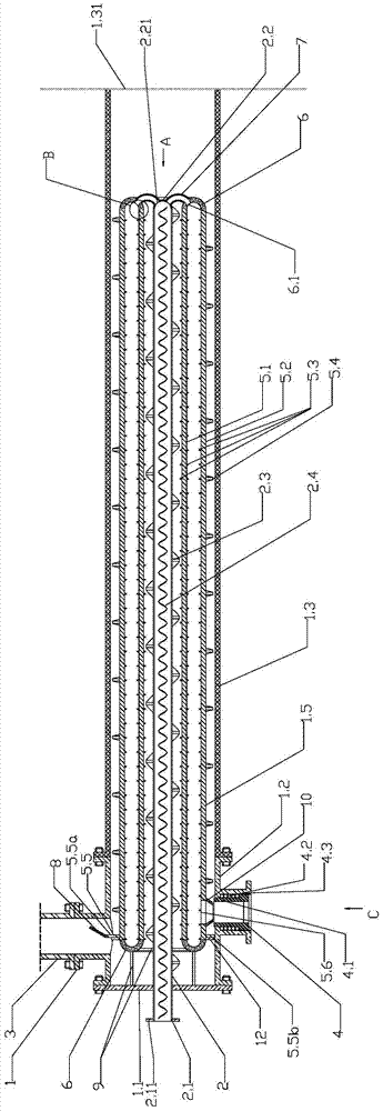
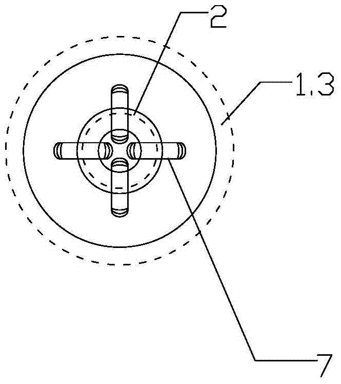
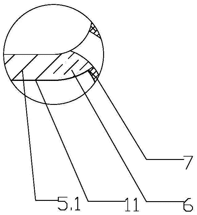
[0036] like Figure 1~4 As shown, a high-efficiency heat exchanger for a non-self-preheating gas burner type radiant tube is located in the smoke exhaust section of the radiant tube. The heat exchanger includes a shell 1, and the shell 1 includes connecting flanges 1.1 connected in sequence , an exhaust pipe 1.2 and a radiant pipe 1.3; the other end of the radiant pipe 1.3 is provided with a flue gas inlet 1.31; A heat exchange inner tube 2 is provided, the center line of the heat exchange inner tube 2 coincides with the center line of the shell 1, and the combustion air inlet 2.1 at one end of the heat exchange inner tube 2 passes through the connecting flange 1.1 and extends out of the shell 1 In addition, the other end port of ...


PUM


Abstract

The invention discloses a high-efficiency heat exchanger for a non-self-preheating gas burner type radiant tube, which is located in the smoke exhaust section of the radiant tube. The heat exchanger includes a shell, and the shell includes sequentially connected connections. Flange, exhaust pipe and radiant pipe; the other end of the radiant pipe is provided with a smoke inlet; the side wall of the exhaust pipe is respectively equipped with a smoke exhaust pipe and a combustion air outlet pipe; A heat exchange inner tube is provided, and a plurality of heat exchange jackets parallel to the heat exchange inner tube are uniformly installed around the heat exchange inner tube. In summary, the present invention through the processing and preparation of gas radiant tube high-efficiency heat exchangers enables various high-efficiency heat exchange technologies and control means to be directly solidified into gas radiant tube heat exchanger products, and through the on-site processing of gas radiant tube high-efficiency heat exchangers Installation and commissioning, optimize the distribution of flue gas flow in the heat exchanger and the volume of entrainment and circulation flue gas, realize the efficient operation of the heat exchanger, and improve the efficiency of flue gas waste heat recovery.

Description

technical field [0001] The invention relates to the technical field of gas radiant tube heating, in particular to a high-efficiency heat exchanger for non-self-preheating gas burner type radiant tubes. Background technique [0002] The indirect heating of the radiant tube isolates the heating workpiece in the furnace from the contact with the combustion gas, avoiding the high temperature corrosion of the heating workpiece by the combustion gas, so it is widely used in industrial furnaces that need to be heated under atmosphere protection conditions, such as continuous heat treatment furnaces for strip steel. [0003] The earliest radiant tube furnace was invented and used in Germany in the 1930s. Its structure is a single-layer straight tube, which is arranged horizontally or vertically through the furnace. It was not until the early 1950s that the U-shaped radiant tube came out and developed on this basis. W-type and P-type and O-type for exhaust gas recirculation. Due to ...

Claims


Application Information

Patent Timeline
Patent Type & Authority Patents(China)
IPC IPC(8): F28D7/10F28F13/06
Inventor 欧阳德刚罗安智罗巍曾彤
Owner 武汉钢铁有限公司
Learn More