
A mechanical disturbance driven submerged liquid-cooled sintered capillary core copper-based heat sink

A technology of heat dissipation device and capillary core, which is applied in furnace cooling, indirect heat exchanger, maintenance of heating chamber, etc., can solve the problems of uneven and insufficient cooling medium replenishment, difficulty in separation of phase change bubbles, etc., and achieves an increase in the contact area. Large, prevent the effect of local hot spots

Active Publication Date: 2022-06-07
XI AN JIAOTONG UNIV
View PDF0 Cites 0 Cited by
  • Summary
  • Abstract
  • Description
  • Claims
  • Application Information

AI Technical Summary

Problems solved by technology

[0003] The purpose of the present invention is to provide a mechanical disturbance driven submerged liquid-cooled sintered capillary core copper-based heat dissipation device to overcome the existing ubiquitous problems such as difficulty in detaching phase-change bubbles in the capillary core, uneven and insufficient replenishment of cooling working fluid, etc. The invention promotes the liquid flow in the immersion chamber, enhances the contact between the liquid and the heat exchange condensation surface; and ensures the heat dissipation structure in The relative separation of the phase change vapor-liquid channel is realized at a relatively high two-phase flow rate with a relatively small thermal resistance and heat hysteresis; by enhancing the liquid replenishment effect of the heat exchange surface, reducing the gas overflow resistance, and increasing the number of boiling nucleation sites, It can significantly improve the phase change heat capacity and working stability of the device under medium and high heat flow

Method used


Image

  • A mechanical disturbance driven submerged liquid-cooled sintered capillary core copper-based heat sink
  • A mechanical disturbance driven submerged liquid-cooled sintered capillary core copper-based heat sink
  • A mechanical disturbance driven submerged liquid-cooled sintered capillary core copper-based heat sink

Examples


Embodiment Construction

[0035] The following embodiments of the present invention will be further described in detail:

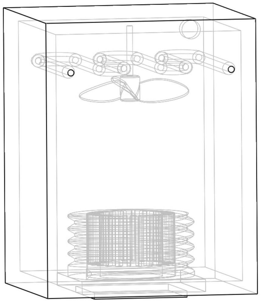
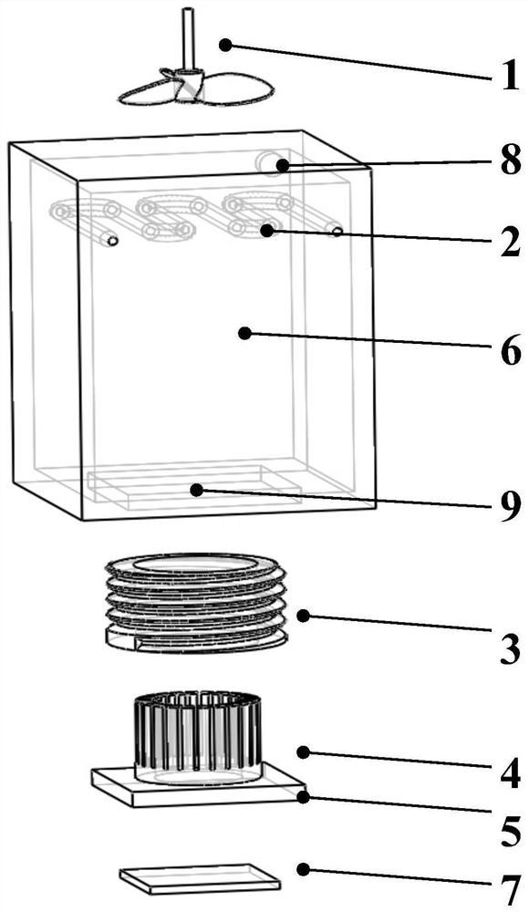
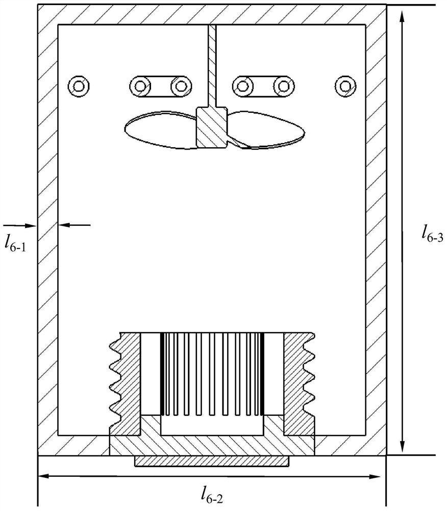
[0036] A kind of mechanical disturbance drive immersion type liquid cooled sintered capillary core copper-based heat dissipation device, such as Figure 1-1 、 1-2 Shown, including disturbance vane 1, cooling coil 2, spiral sintered capillary core 3, annular rib group 4, square vapor plate 5, external cavity 6, heat dissipation chip 7, external cavity 6 with rehydration port 8 and parts opening 9.

[0037]The device can be divided into three parts: mechanical power strengthening heat transfer part based on disturbance blade 1; The surface structure strengthens the heat transfer part and other auxiliary parts represented by spiral sintered capillary core 3, annular rib group 4, and square vaporized plate 5. The mechanical power of the disturbing blade 1 will effectively drive the flow of liquid in the cavity when it is in operation, promote the mixing and exchange of heat with the cooling...


PUM

PropertyMeasurementUnit
angleaaaaaaaaaa
lengthaaaaaaaaaa
widthaaaaaaaaaa

Abstract

The invention discloses a mechanical disturbance driven submerged liquid-cooled sintered capillary core copper-based heat dissipation device, which comprises a disturbance vane, a cooling coil, a spiral sintered capillary core, an annular rib group, a square soaking plate, an outer cavity and a heat dissipation chip The disturbance vane is connected to the inner top of the outer cavity through a transmission shaft, the cooling coil is located between the inner top of the outer cavity and the disturbance vane, and the inner side of the spiral sintered capillary core is sintered into one with the annular rib group, The outer side is threaded, and the annular rib group is connected to the top surface of the square soaking plate, and the square soaking plate is embedded in the bottom of the outer cavity, and the spiral sintered capillary core and the annular fin group are located inside the outer cavity , the ring-shaped fin group includes several fins arranged in a ring, and the distance between adjacent fins is equal, the top surface of the heat dissipation chip is in firm contact with the bottom surface of the square chamber, and the side of the outer cavity is also provided with There is a rehydration port.

Description

Technical field [0001] The present invention relates to a sintered structure of a micron heat transfer in a micron heat transfer structure to enhance the field of phase change heat transfer, specifically relates to a mechanical disturbance drive immersion type liquid cold sintered capillary core copper-based heat dissipation device. Background [0002] With the rapid development of the semiconductor chip industry, the high-throughput heat flow generated by the operation of the electronic device cluster is gradually increasing the requirements for the heat sink to strengthen the heat transfer capacity, and the traditional air cooling and heat pipe cooling are powerless to channel the large heat flow in a small area. Boiling heat exchange is through a large number of liquids violently vaporized, so that the heat generated by the system through the absorption of vaporized latent heat effective transfer, low-cost strengthening surface research and parameter optimization is an essenti...

Claims


Application Information

Patent Timeline
Patent Type & Authority Patents(China)
IPC IPC(8): F28D15/04F27B17/00F27D7/04F27D9/00
CPCF28D15/046F27B17/0016F27D9/00F27D7/04F27D2009/0081F27D2007/045Y02D10/00
Inventor 张永海刘万渤杨小平魏进家
Owner XI AN JIAOTONG UNIV
Learn More