Er/Yb co-doped fiber for improving 1.5 mum laser efficiency

An optical fiber and high-efficiency technology, which is applied in the direction of multi-layer core/cladding optical fiber, cladding optical fiber, microstructure optical fiber, etc., can solve the problems of increasing laser output power, achieve suppression of parasitic oscillation, wide practicability, and good use effect Effect

Active Publication Date: 2015-12-16
XUZHOU NORMAL UNIVERSITY
View PDF3 Cites 10 Cited by
  • Summary
  • Abstract
  • Description
  • Claims
  • Application Information

AI Technical Summary

Problems solved by technology

However, this also brings problems: In 2007, Y. Jeong et al. showed in the article "Erbium: Ytterbium Codoped Large-CoreFiberLaserWith297-WContinuous-WaveOutputPower" in IEEE Journal of Selected Topics in Quantum Electronics, vol. The maximum output power of the laser is 297W, and the output power of the ~1μm laser is as high as 338W, which exceeds the output power of th

Method used


Image

  • Er/Yb co-doped fiber for improving 1.5 mum laser efficiency
  • Er/Yb co-doped fiber for improving 1.5 mum laser efficiency
  • Er/Yb co-doped fiber for improving 1.5 mum laser efficiency

Examples


Embodiment example 1

[0034] The technical indicators and basic performance parameters are as follows:

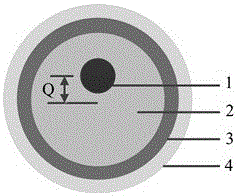
[0035] 1. Central axis offset .

[0036] 2. The diameter of the fiber core is 30 μm, the effective refractive index is 1.538, and the numerical aperture (NA) is 0.08.

[0037] 3. The diameter of the inner cladding is 400 μm, the effective refractive index is 1.536, and the numerical aperture (NA) is 0.4.

[0038] 4. The diameter of the outer cladding is 550 μm.

[0039] 5. The diameter of the coating layer is 700 μm.

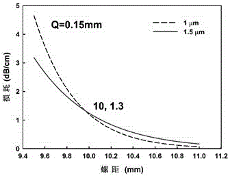
[0040] At this time, the bending loss of the fiber at 1 μm and 1.5 μm varies with the pitch The theoretical simulation diagram of the change is shown in image 3 As shown, it can be clearly seen that when When , the fiber loss in the 1 μm band is greater than that in the 1.5 μm band, which can effectively suppress the parasitic oscillation in the 1 μm band.

Embodiment example 2

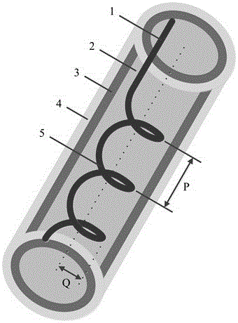
[0042] The structure of the spiral core fiber is as figure 1 and figure 2 shown, the center axis offset , at this time, the bending loss of the fiber at 1 μm and 1.5 μm varies with the pitch The theoretical simulation diagram of the change is shown in Figure 4 As shown, it can be clearly seen that when When , the fiber loss in the 1 μm band is greater than that in the 1.5 μm band, which can effectively suppress the parasitic oscillation in the 1 μm band.

Embodiment example 3

[0044] The structure of the spiral core fiber is as figure 1 and figure 2 shown, the center axis offset , at this time, the bending loss of the fiber at 1 μm and 1.5 μm varies with the pitch The theoretical simulation diagram of the change is shown in Figure 4 As shown, it can be clearly seen that when When , the fiber loss in the 1 μm band is greater than that in the 1.5 μm band, which can effectively suppress the parasitic oscillation in the 1 μm band.

[0045] In summary, the present invention proposes an Er, Yb co-doped spiral core fiber, by adjusting the central axis offset Q and pitch P , can change the fiber loss corresponding to different wavelengths, so that the fiber loss in the 1μm band is greater than the fiber loss in the 1.5μm band, and achieve the effect of suppressing 1μm parasitic oscillation.


PUM

PropertyMeasurementUnit
Diameteraaaaaaaaaa
Diameteraaaaaaaaaa
Diameteraaaaaaaaaa

Abstract

The invention relates to an Er/Yb co-doped fiber for improving 1.5 mum laser efficiency, and is suitable for the laser communication field. The fiber comprises a fibre core, an inner wrapping layer, an outer wrapping layer and a coating layer from the inside out. The fibre core is formed by straight core and a section of spiral core; and fibre loss can be changed by adjusting spiral pitch of the spiral core and offset amount of a center shaft, and thus fibre loss in 1 mum wave band is allowed to be larger than fibre loss in 1.5 mum wave band. The features above allow the Er/Yb co-doped fiber to be applied to a high-power Er/Yb co-doped fiber laser, and thus the problem of 1 mum parasitic oscillation is effectively solved, and 1.5 mum laser output power is improved.

Description

technical field [0001] The invention relates to an Er, Yb co-doped optical fiber, in particular to an Er, Yb co-doped optical fiber for improving laser efficiency of ~1.5 μm in the technical field of laser communication. Background technique [0002] The ~1.5μm band belongs to the safe band for human eyes and is in the atmospheric window. Therefore, lasers in this band are widely used in laser communication, ranging, medical treatment, industrial processing and other fields. The current main method to generate the ~1.5μm band is doping Er 3+ Fiber lasers and bulk gain medium solid-state lasers. Compared with traditional bulk laser gain medium solid-state lasers, fiber lasers have the advantages of compact structure, good beam quality, high laser efficiency, and simple thermal management. The existing optical fiber structure includes a core, an inner cladding, an outer cladding, and a coating layer from the inside to the outside. 3+ The gain fiber has low absorption effici...

Claims


Application Information

Patent Timeline
IPC IPC(8): G02B6/036G02B6/02
CPCG02B6/02295G02B6/03633
Inventor 沈德元赵永光陈碧辉周伟陈浩
Owner XUZHOU NORMAL UNIVERSITY
Why Eureka
Try Eureka