Memristor based on fiber substrate and preparation method of memristor
A fiber substrate and memristor technology, applied in electrical components and other directions, can solve the problems of high cost and inflexibility, and achieve the effects of low cost, easy extraction and light weight
- Summary
- Abstract
- Description
- Claims
- Application Information
AI Technical Summary
Problems solved by technology
Method used
Image

Examples
preparation example Construction
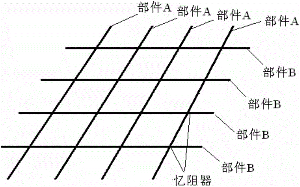
[0049] The preparation process process steps of the memristor of the present invention are as follows:
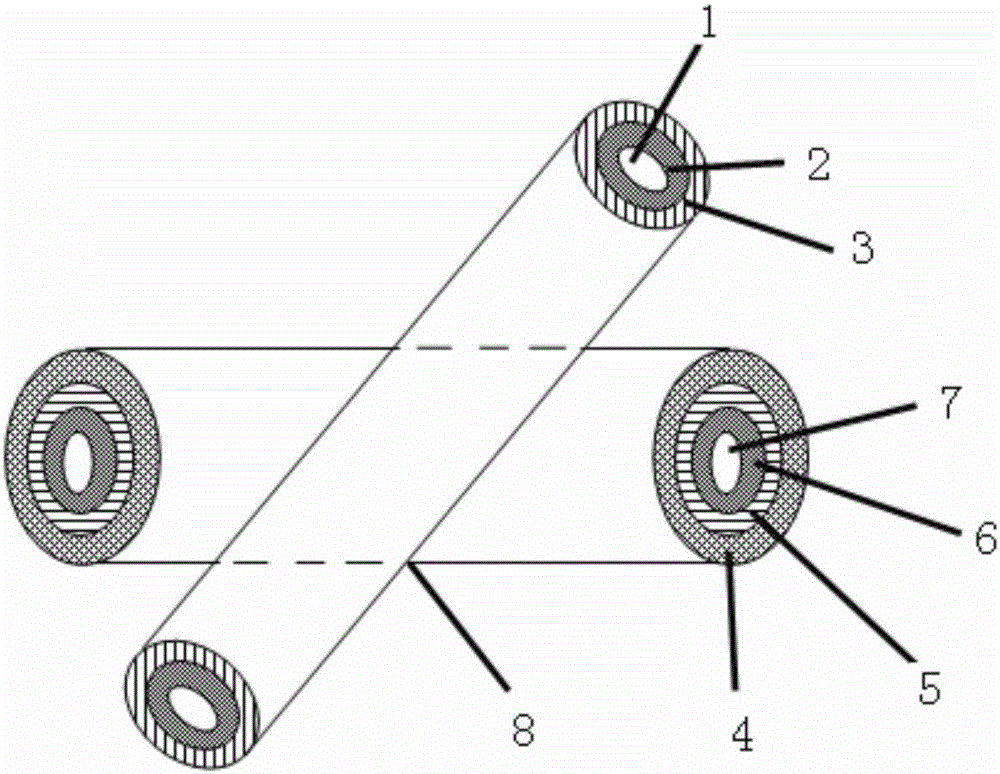
[0050] Step 1: using fiber 1 as flexible substrate I and fiber 4 as flexible substrate II;
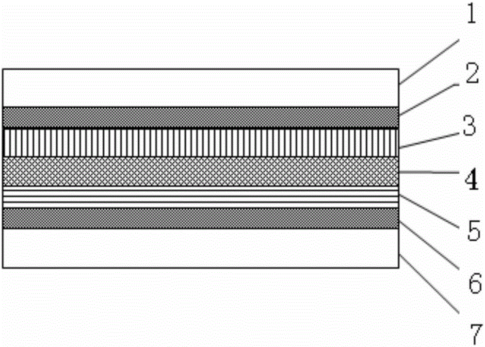
[0051] Step 2: Sputter a layer of Ta on the substrate I first, because Ta absorbs part of the natural oxide at the contact, reduces the contact resistance, and thus improves the adhesion to the electrode. Nitrogen gas is introduced while Ta is sputtered, and the process parameters are well controlled to form a TaN film with a thickness of about 100nm;
[0052] Step 3: adopt the same method as Step 2 to form a TaN film with a thickness of about 100 nm on the substrate II;
[0053] Step 4: On the TaN film (isolation layer 1) of the substrate 1, any one of epitaxy, chemical vapor deposition, electron beam evaporation, pulsed laser deposition, atomic layer deposition or magnetron sputtering Deposit a layer of conductive thin film with a thickness of 50nm-800nm on it, and form an upp...
Embodiment 1
[0059] Both fiber 1 and fiber 4 are carbon fibers; the upper electrode material is Pt with a thickness of 200nm; the lower electrode material is Ag film with a thickness of 400nm; the storage medium layer is NiO with a thickness of 200nm.
Embodiment 2
[0061] Both fiber 1 and fiber 4 are glass fibers; the upper electrode material is Cu with a thickness of 800nm; the lower electrode material is W with a thickness of 50nm; the storage medium layer is Dy 2 o 3 , with a thickness of 50nm;
PUM
| Property | Measurement | Unit |
|---|---|---|
| Thickness | aaaaa | aaaaa |
| Thickness | aaaaa | aaaaa |
| Thickness | aaaaa | aaaaa |
Abstract
Description
Claims
Application Information